
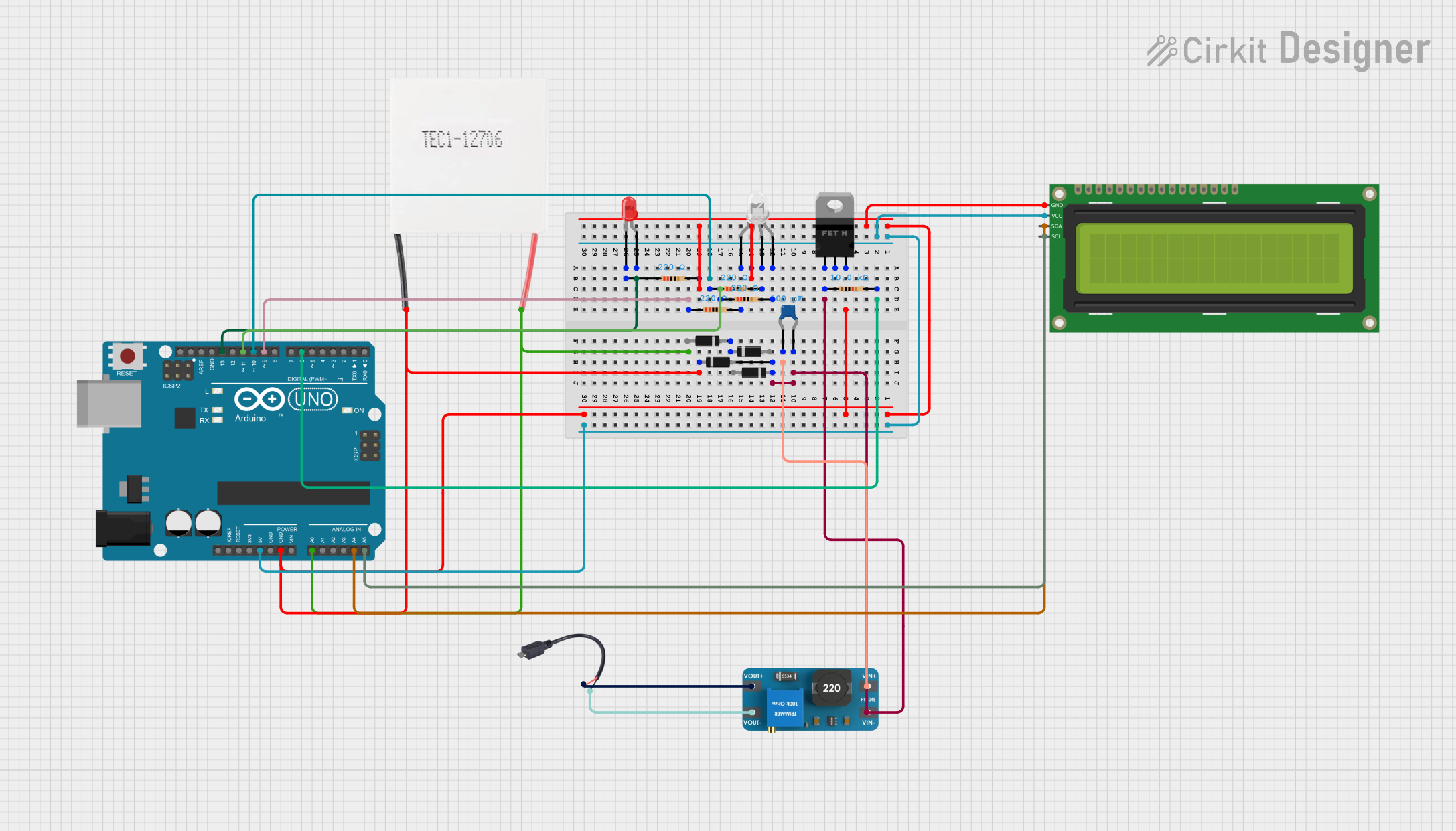
Circuit Documentation
Summary
This document provides a detailed overview of a circuit that includes an Arduino UNO microcontroller, a Peltier module, various LEDs, resistors, diodes, a ceramic capacitor, a boost converter, a micro USB cable, an I2C LCD, and an nMOS transistor. The circuit is designed to control and monitor various components using the Arduino UNO.
Component List
Arduino UNO
- Description: Microcontroller board based on the ATmega328P.
- Pins: UNUSED, IOREF, Reset, 3.3V, 5V, GND, Vin, A0, A1, A2, A3, A4, A5, SCL, SDA, AREF, D13, D12, D11, D10, D9, D8, D7, D6, D5, D4, D3, D2, D1, D0
Peltier Module
- Description: Thermoelectric cooler.
- Pins: Negative, Positive
LED: Two Pin (red)
- Description: Red LED with two pins.
- Pins: Cathode, Anode
Resistor (220 Ohms)
- Description: Resistor with a resistance of 220 Ohms.
- Pins: Pin1, Pin2
Resistor (10k Ohms)
- Description: Resistor with a resistance of 10k Ohms.
- Pins: Pin1, Pin2
Diode
- Description: General-purpose diode.
- Pins: Cathode, Anode
Ceramic Capacitor (0.0001 Farads)
- Description: Capacitor with a capacitance of 0.0001 Farads.
- Pins: Pin0, Pin1
Boost Converter MT3608
- Description: DC-DC step-up converter.
- Pins: OUTPUT +, OUTPUT -, INPUT +, INPUT -
Micro USB to Cable (2 Pin)
- Description: Micro USB to 2-pin cable.
- Pins: Micro USB, +, -
16x2 I2C LCD
- Description: 16x2 character LCD with I2C interface.
- Pins: GND, VCC, SDA, SCL
nMOS Transistor (MOSFET)
- Description: n-channel MOSFET.
- Pins: Gate, Drain, Source
LED: Four Pin (Common Cathode)
- Description: RGB LED with common cathode.
- Pins: Red Anode, Common Cathode, Green Anode, Blue Anode
Wiring Details
Arduino UNO
- D6 connected to Resistor (10k Ohms) Pin2
- GND connected to:
- nMOS Transistor (MOSFET) Source
- Diode Cathode
- Peltier Module Negative
- LED: Four Pin (Common Cathode) Common Cathode
- Resistor (220 Ohms) Pin2
- 16x2 I2C LCD GND
- D11 connected to Resistor (220 Ohms) Pin1
- D10 connected to Resistor (220 Ohms) Pin1
- D9 connected to Resistor (220 Ohms) Pin1
- A0 connected to Peltier Module Positive
- D13 connected to LED: Two Pin (red) Anode
- 5V connected to 16x2 I2C LCD VCC
- A4 connected to 16x2 I2C LCD SDA
- A5 connected to 16x2 I2C LCD SCL
Peltier Module
- Negative connected to Arduino UNO GND
- Positive connected to Arduino UNO A0
LED: Two Pin (red)
- Anode connected to Arduino UNO D13
- Cathode connected to Resistor (220 Ohms) Pin1
Resistor (220 Ohms)
- Pin1 connected to LED: Two Pin (red) Cathode
- Pin2 connected to Arduino UNO GND
Resistor (10k Ohms)
- Pin1 connected to nMOS Transistor (MOSFET) Gate
- Pin2 connected to Arduino UNO D6
Diode
- Cathode connected to:
- nMOS Transistor (MOSFET) Source
- Diode Cathode
- Anode connected to:
- nMOS Transistor (MOSFET) Gate
- Diode Cathode
- Ceramic Capacitor Pin1
- Boost Converter MT3608 INPUT -
Ceramic Capacitor (0.0001 Farads)
- Pin0 connected to Boost Converter MT3608 INPUT +
- Pin1 connected to Diode Anode
Boost Converter MT3608
- OUTPUT + connected to Micro USB to Cable (2 Pin) +
- OUTPUT - connected to Micro USB to Cable (2 Pin) -
- INPUT + connected to Ceramic Capacitor Pin0
- INPUT - connected to Diode Anode
Micro USB to Cable (2 Pin)
- + connected to Boost Converter MT3608 OUTPUT +
- - connected to Boost Converter MT3608 OUTPUT -
16x2 I2C LCD
- GND connected to Arduino UNO GND
- VCC connected to Arduino UNO 5V
- SDA connected to Arduino UNO A4
- SCL connected to Arduino UNO A5
nMOS Transistor (MOSFET)
- Gate connected to Resistor (10k Ohms) Pin1
- Source connected to Arduino UNO GND
LED: Four Pin (Common Cathode)
- Common Cathode connected to Arduino UNO GND
- Red Anode connected to Resistor (220 Ohms) Pin2
- Green Anode connected to Resistor (220 Ohms) Pin2
- Blue Anode connected to Resistor (220 Ohms) Pin2
Code Documentation
Arduino UNO Code
void setup() {
  // put your setup code here, to run once:

}

void loop() {
  // put your main code here, to run repeatedly:

}
This code is a basic template for the Arduino UNO. The setup() function is used to initialize any settings or configurations, and the loop() function contains the main code that runs repeatedly. Currently, both functions are empty and can be filled with the desired logic for controlling the circuit components.