Cirkit Designer
Your all-in-one circuit design IDE
Home /
Project Documentation
ESP8266 NodeMCU Based Smart Garden Monitoring System with I2C LCD Display
Circuit Documentation
Summary
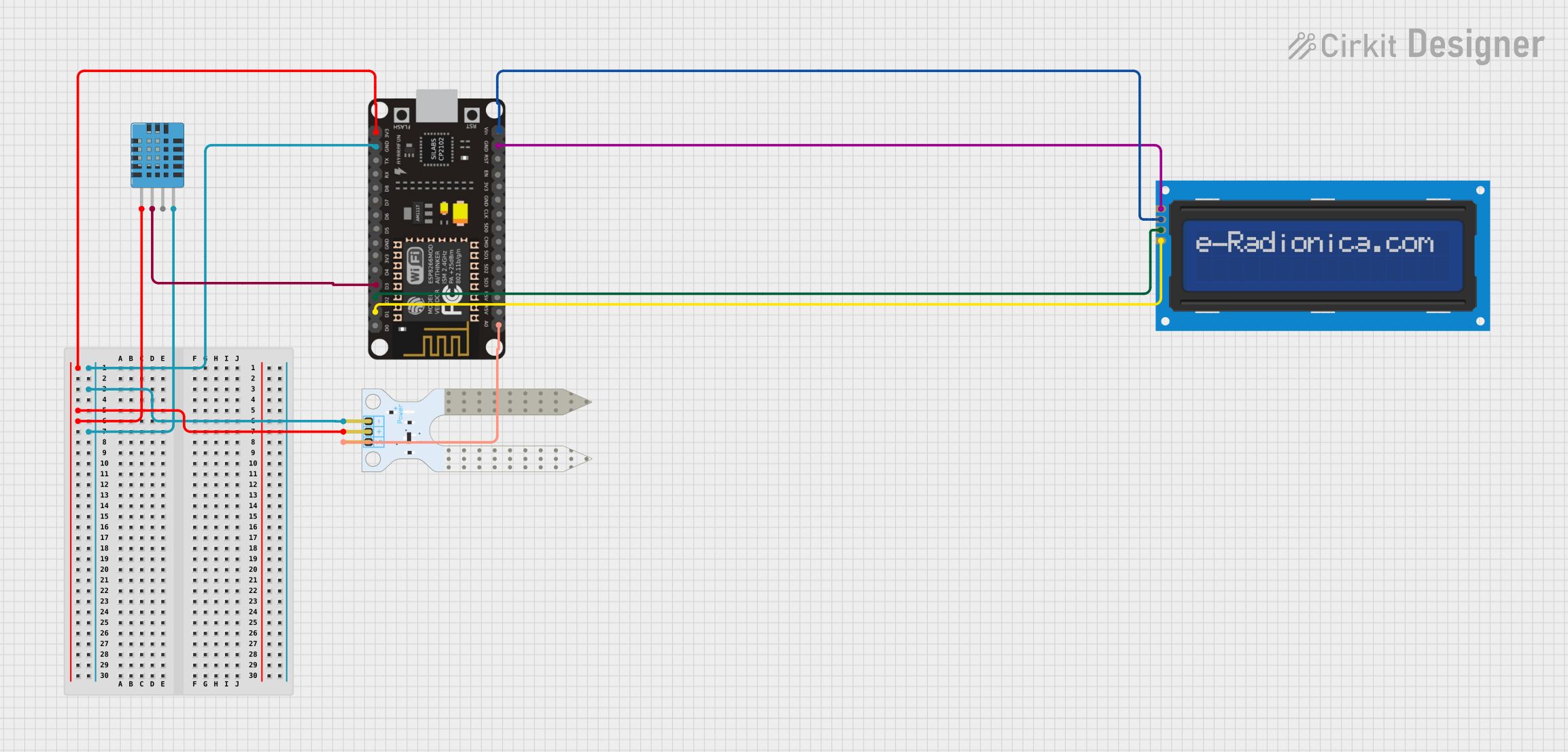
This circuit is designed to monitor environmental parameters such as temperature, humidity, and soil moisture levels. It utilizes an ESP8266 NodeMCU microcontroller to read data from a DHT11 temperature and humidity sensor and a soil moisture sensor. The readings are displayed on a 16x2 I2C LCD screen. The ESP8266 NodeMCU is responsible for controlling the sensors, processing the data, and updating the display.
Component List
ESP8266 NodeMCU
- Description: A WiFi-capable microcontroller module based on the ESP8266 chip.
- Pins: D0, D1, D2, D3, D4, 3V3, GND, D5, D6, D7, D8, RX, TX, A0, RSV, SD3, SD2, SD1, CMD, SD0, CLK, EN, RST, VIN
LCD Screen 16x2 I2C
- Description: A 16-character by 2-line display with an I2C interface.
- Pins: SCL, SDA, VCC, GND
DHT11 Humidity and Temperature Sensor
- Description: A basic, low-cost digital temperature and humidity sensor.
- Pins: VDD, DATA, NULL, GND
Soil Moisture Sensor
- Description: A sensor that measures the volumetric content of water in soil.
- Pins: VCC, GND, SIG
Wiring Details
ESP8266 NodeMCU
- 3V3: Connected to the VCC of the Soil Moisture Sensor and VDD of the DHT11 Sensor.
- GND: Common ground with the Soil Moisture Sensor, DHT11 Sensor, and LCD Screen.
- D1 (SCL): Connected to the SCL pin of the LCD Screen.
- D2 (SDA): Connected to the SDA pin of the LCD Screen.
- VIN: Connected to the VCC pin of the LCD Screen.
- D3: Connected to the DATA pin of the DHT11 Sensor.
- A0: Connected to the SIG pin of the Soil Moisture Sensor.
LCD Screen 16x2 I2C
- SCL: Connected to D1 (SCL) on the ESP8266 NodeMCU.
- SDA: Connected to D2 (SDA) on the ESP8266 NodeMCU.
- VCC: Connected to VIN on the ESP8266 NodeMCU.
- GND: Common ground with the ESP8266 NodeMCU.
DHT11 Humidity and Temperature Sensor
- VDD: Connected to 3V3 on the ESP8266 NodeMCU.
- DATA: Connected to D3 on the ESP8266 NodeMCU.
- GND: Common ground with the ESP8266 NodeMCU.
Soil Moisture Sensor
- VCC: Connected to 3V3 on the ESP8266 NodeMCU.
- GND: Common ground with the ESP8266 NodeMCU.
- SIG: Connected to A0 on the ESP8266 NodeMCU.
Documented Code
/*
 * This Arduino Sketch reads temperature and humidity from a DHT11 sensor,
 * soil moisture levels from a soil moisture sensor, and displays the
 * readings on a 16x2 I2C LCD screen using an ESP8266 NodeMCU.
 */

#include <Wire.h>
#include <LiquidCrystal_I2C.h>
#include <DHT.h>

// LCD I2C address and dimensions
#define LCD_ADDR 0x27
#define LCD_COLS 16
#define LCD_ROWS 2

// DHT11 sensor settings
#define DHTPIN D3
#define DHTTYPE DHT11
DHT dht(DHTPIN, DHTTYPE);

// Soil moisture sensor pin
#define SOIL_MOISTURE_PIN A0

// Initialize the LCD
LiquidCrystal_I2C lcd(LCD_ADDR, LCD_COLS, LCD_ROWS);

void setup() {
  // Initialize serial communication
  Serial.begin(115200);

  // Initialize the DHT sensor
  dht.begin();

  // Initialize the LCD
  lcd.begin();
  lcd.backlight();
  lcd.clear();
  lcd.setCursor(0, 0);
  lcd.print("Initializing...");
}

void loop() {
  // Read temperature and humidity from DHT11
  float humidity = dht.readHumidity();
  float temperature = dht.readTemperature();

  // Read soil moisture level
  int soilMoistureValue = analogRead(SOIL_MOISTURE_PIN);
  float soilMoisturePercent = map(soilMoistureValue, 0, 1023, 0, 100);

  // Check if any reads failed and exit early (to try again)
  if (isnan(humidity) || isnan(temperature)) {
    Serial.println("Failed to read from DHT sensor!");
    return;
  }

  // Print readings to the LCD
  lcd.clear();
  lcd.setCursor(0, 0);
  lcd.print("Temp: ");
  lcd.print(temperature);
  lcd.print(" C");

  lcd.setCursor(0, 1);
  lcd.print("Hum: ");
  lcd.print(humidity);
  lcd.print(" %");

  lcd.setCursor(8, 1);
  lcd.print("Soil: ");
  lcd.print(soilMoisturePercent);
  lcd.print(" %");

  // Wait a few seconds between measurements
  delay(2000);
}
This code is responsible for initializing the sensors and the LCD screen, reading the sensor data, and displaying the information on the LCD. It includes error handling for failed sensor reads and uses a delay to space out the readings.