Cirkit Designer
Your all-in-one circuit design IDE
Home /
Project Documentation
Ghostbusters Trap Simulation with Arduino Mega and Adafruit Modules

Circuit Documentation
Summary
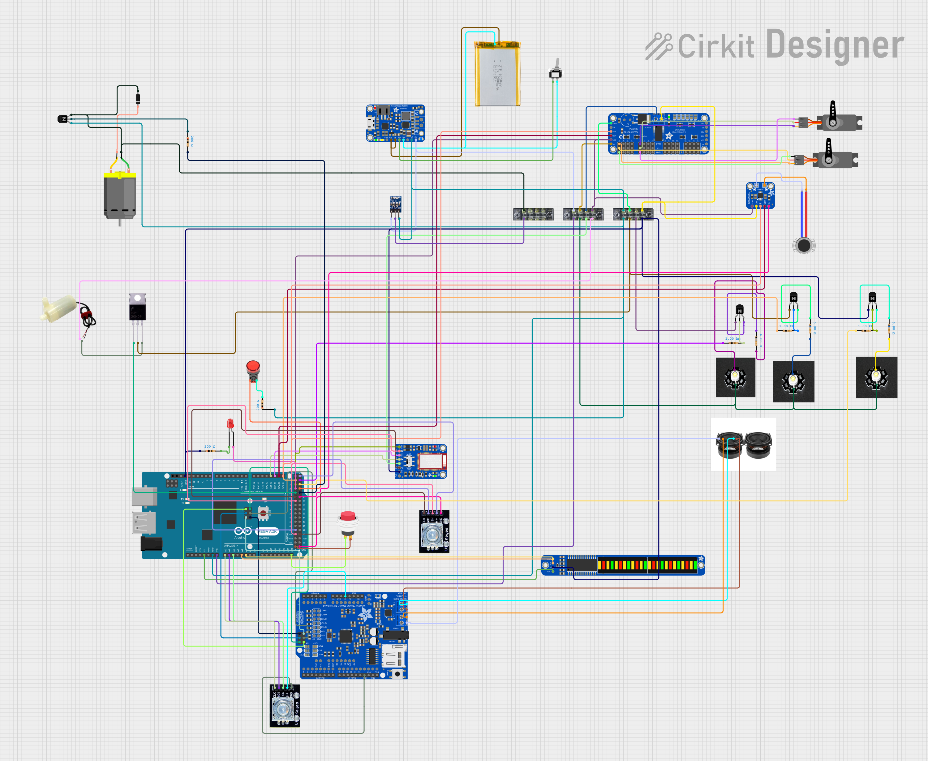
The circuit is designed to simulate a ghost trap from the movie Ghostbusters. It features a variety of components including servos, LEDs, a bargraph, a haptic motor, a DC motor, and a water pump to create an effect of a ghost being trapped and the trap experiencing an electrical failure. The sequence can be activated by a Bluetooth input or an encoder knob switch. The encoder knob also controls the volume. The circuit is controlled by an Arduino Mega ADK microcontroller.
Component List
- Adafruit 16-Channel 12-bit PWM Servo Driver - I2C: Used to drive multiple PWM servos.
- Adafruit DRV2605L: A haptic controller for vibration motors.
- Vibration Motor: Provides haptic feedback.
- Servo: Actuators for moving parts of the trap.
- Adafruit PowerBoost 1000C: A power supply module for battery charging and 5V regulation.
- Mosfet: Used to switch higher current loads with a microcontroller.
- 5v mini water pump: Simulates the effect of the ghost being trapped.
- Lamp Red: Provides visual indication.
- Adafruit Bi-Color 24-Bar Bargraph w/ I2C Backpack: Displays visual information.
- LED: Two Pin (red): Simple indicator LED.
- Resistor: Used for current limiting and pull-up/down resistors.
- Rotary Encoder: Provides user input for control and volume adjustment.
- DC Motor: Used to simulate mechanical movements.
- Diode: Prevents back EMF from the DC motor.
- NPN Transistor (EBC): Used as a switch for controlling various components.
- Speaker: Outputs audio signals.
- Adafruit Music Maker Shield with Amp: Handles audio playback and amplification.
- Adafruit Bluefruit LE UART Friend: Provides Bluetooth connectivity.
- 2Pin Push Switch: A simple push button switch.
- 1 Watt LED Cool White w/ Heatsink: High-power LEDs for bright visual effects.
- Arduino Mega ADK (Rev3): The main microcontroller board that controls the circuit.
- 2000mAh Battery: Provides power to the circuit.
- Terminal Block: Used for making easy connections to the board.
- Toggle Switch SPST: A single-pole single-throw switch for power control.
- AMS1117 3.3: A voltage regulator for providing 3.3V.
Wiring Details
Adafruit 16-Channel 12-bit PWM Servo Driver - I2C
5.0VandVCCconnected to 5V power supply.SDAandSCLconnected to I2C bus (Arduino Mega ADK).OEnot connected.GNDconnected to ground.PWM0toPWM15connected to servos and other PWM devices.
Adafruit DRV2605L
VINconnected to 5V power supply.GNDconnected to ground.SCLandSDAconnected to I2C bus (Arduino Mega ADK).IN/TRIGconnected to digital pin D31 (Arduino Mega ADK).OUT+andOUT-connected to Vibration Motor.
Vibration Motor
POSconnected toOUT+on Adafruit DRV2605L.NEGconnected toOUT-on Adafruit DRV2605L.
Servo
GNDconnected to ground.VCCconnected to 5V power supply.PWMconnected to PWM output from Adafruit 16-Channel PWM Servo Driver.
Adafruit PowerBoost 1000C
GNDconnected to ground.5.0Vconnected to 5V power supply.VBUSandVLIPOconnected to 2000mAh Battery.ENABLEconnected to Toggle Switch SPST.
Mosfet
Gateconnected to digital pin D28 (Arduino Mega ADK).Drainconnected to 5v mini water pump and NPN Transistor (EBC).Sourceconnected to ground.
5v mini water pump
positive pinconnected to Mosfet.negative pinconnected to ground.
Lamp Red
+connected to digital pin D27 (Arduino Mega ADK).-connected to ground through a resistor.
Adafruit Bi-Color 24-Bar Bargraph w/ I2C Backpack
VDDconnected to 5V power supply.GNDconnected to ground.SDAandSCLconnected to I2C bus (Arduino Mega ADK).
LED: Two Pin (red)
cathodeconnected to ground through a resistor.anodeconnected to digital pin D26 (Arduino Mega ADK).
Resistor
- Connected in series with LEDs and other components for current limiting.
Rotary Encoder
clkanddtconnected to digital pins A0 and A1 (Arduino Mega ADK).swconnected to digital pin A2 (Arduino Mega ADK).gndconnected to ground.+connected to 5V power supply.
DC Motor
- One pin connected to NPN Transistor (EBC) collector.
- Other pin connected to ground through a diode.
Diode
cathodeconnected to DC Motor.anodeconnected to NPN Transistor (EBC) collector.
NPN Transistor (EBC)
emitterconnected to ground.baseconnected to digital pins D22, D23, D25 (Arduino Mega ADK) through resistors.collectorconnected to various components like DC Motor, Diode, and LEDs.
Speaker
+and-connected to Adafruit Music Maker Shield with Amp.
Adafruit Music Maker Shield with Amp
- Connected to Arduino Mega ADK through ICSP and digital pins for control and data transfer.
Adafruit Bluefruit LE UART Friend
MODE,CTS,TXO,RXI,VIN,RTS,GND,DFUconnected to corresponding pins on Arduino Mega ADK for Bluetooth communication.
2Pin Push Switch
Input +connected to digital pin A15 (Arduino Mega ADK).Output +connected to ground.
1 Watt LED Cool White w/ Heatsink
Positiveconnected to 5V power supply.Negativeconnected to ground through NPN Transistor (EBC) and resistors.
Arduino Mega ADK (Rev3)
- Various digital and analog pins connected to components as described above.
5VandGNDused to power components and provide ground reference.VINconnected to 5V power supply.
2000mAh Battery
VCCconnected to Adafruit PowerBoost 1000C.GNDconnected to ground.
Terminal Block
- Used for organizing connections to various components.
Toggle Switch SPST
L1connected to Adafruit PowerBoost 1000CENABLE.COMconnected to ground.
AMS1117 3.3
VINconnected to 5V power supply.OUTconnected to 3.3V components.GNDconnected to ground.
Documented Code
/*
 * Ghostbusters Trap Simulation
 * This code simulates a ghost trap from the movie Ghostbusters.
 * It controls servos, LEDs, a bargraph, a haptic motor, a DC motor,
 * and a water pump to create an effect of a ghost being trapped
 * and the trap experiencing an electrical failure.
 * The sequence can be activated by a Bluetooth input or the encoder knob switch.
 * The encoder knob also controls the volume.
 */

#include <Adafruit_PWMServoDriver.h>
#include <Adafruit_VS1053.h>
#include <Adafruit_LEDBackpack.h>
#include <Wire.h>
#include <Servo.h>
#include <SoftwareSerial.h>

#define LED_D26 26
#define LED_D27 27
#define LED_D22 22
#define LED_D23 23
#define LED_D25 25
#define SWITCH_PIN 31
#define HAPTIC_PIN 20
#define DC_MOTOR_PIN 29
#define PUMP_PIN 28
#define ENCODER_SW_PIN 48
#define ENCODER_CLK_PIN 49
#define ENCODER_DT_PIN 46
#define BLUETOOTH_RX 18
#define BLUETOOTH_TX 19

Adafruit_PWMServoDriver pwm = Adafruit_PWMServoDriver();
Adafruit_VS1053_FilePlayer musicPlayer = Adafruit_VS1053_FilePlayer();
Adafruit_24bargraph bargraph = Adafruit_24bargraph();
Servo leftServo;
Servo rightServo;
SoftwareSerial bluetooth(BLUETOOTH_TX, BLUETOOTH_RX);

volatile int lastEncoded = 0;
volatile long encoderValue = 0;
long lastencoderValue = 0;
int lastMSB = 0;
int lastLSB = 0;