
Circuit Documentation
Summary of the Circuit
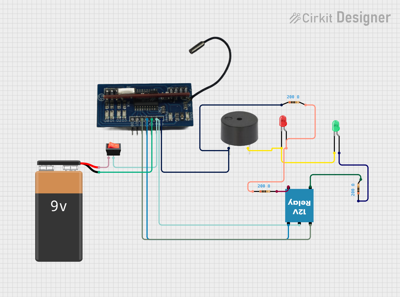
This circuit is designed to control a 12V relay using an RF receiver, which can be triggered by an RF signal. The relay can switch between normally closed (NC) and normally open (NO) states, which can be used to control external devices. The circuit includes a buzzer and two LEDs (green and red) to provide visual and audible indicators of the relay's status. A rocker switch is used to control the power supply from a 9V battery to the RF receiver and the relay. The circuit also includes resistors to limit current to the LEDs and the buzzer.
Component List
RF Receiver
- Pins: D0, D1, D2, D3, GND, VCC
- Description: Receives RF signals and controls the relay accordingly.
LED: Two Pin (green)
- Pins: cathode, anode
- Description: Provides a visual indication when the relay is in the NO state.
LED: Two Pin (red)
- Pins: cathode, anode
- Description: Provides a visual indication when the relay is in the NC state.
12V Relay
- Pins: +, -, C, NC, NO
- Description: Acts as a switch controlled by the RF receiver to toggle between NC and NO states.
Resistor (200 Ohms)
- Pins: pin1, pin2
- Description: Limits the current to the LEDs and the buzzer to prevent damage.
Buzzer
- Pins: PIN, GND
- Description: Provides an audible indication when the relay is activated.
Rocker Switch
- Pins: output, input
- Description: Controls the power supply to the RF receiver and the relay.
9V Battery
- Pins: -, +
- Description: Provides the power source for the circuit.
Wiring Details
RF Receiver
- VCC connected to the rocker switch (output)
- GND connected to the 9V battery (-) and the buzzer (PIN) through a resistor
- D2 connected to the 12V relay (+)
- D3 connected to the 12V relay (-)
LED: Two Pin (green)
- Cathode connected to the buzzer (GND)
- Anode connected to a 200 Ohm resistor (pin1)
LED: Two Pin (red)
- Cathode connected to the buzzer (GND)
- Anode connected to a 200 Ohm resistor (pin1) through another 200 Ohm resistor (pin2)
12V Relay
- C connected to the rocker switch (output)
-
- connected to the RF receiver (D2)
-
- connected to the RF receiver (D3)
- NC connected to a 200 Ohm resistor (pin2)
- NO connected to a 200 Ohm resistor (pin2)
Resistor (200 Ohms)
- One resistor connected between the RF receiver (GND) and the buzzer (PIN)
- One resistor connected between the 12V relay (NC) and the LED: Two Pin (red) (anode)
- One resistor connected between the 12V relay (NO) and the LED: Two Pin (green) (anode)
Buzzer
- PIN connected to the RF receiver (GND) through a resistor
- GND connected to the cathodes of both LEDs
Rocker Switch
- Output connected to the RF receiver (VCC) and the 12V relay (C)
- Input connected to the 9V battery (+)
9V Battery
-
- connected to the rocker switch (input)
-
- connected to the RF receiver (GND)
Documented Code
There is no embedded code provided for the microcontrollers in this circuit. If code is later provided, it will be documented in this section.