
Circuit Documentation
Summary
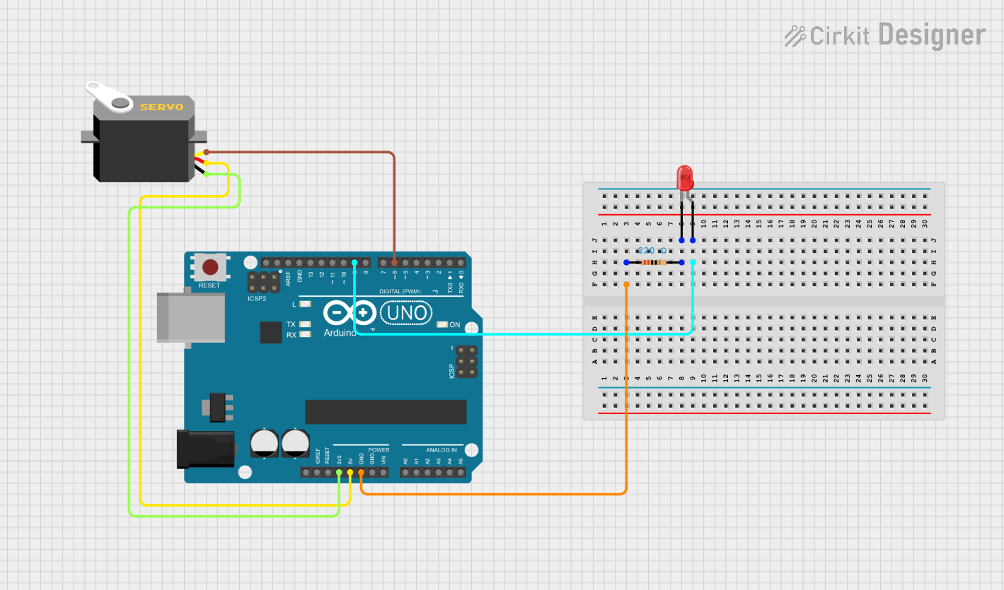
This circuit is designed around an Arduino UNO microcontroller and includes a red two-pin LED, a resistor, and a servo motor. The LED is controlled by one of the digital pins on the Arduino and is connected in series with a resistor to limit the current. The servo motor is controlled by another digital pin and is powered directly from the Arduino's voltage supply pins. The microcontroller runs a program that turns the LED on and off and moves the servo between two positions.
Component List
Arduino UNO
- Description: A microcontroller board based on the ATmega328P.
- Purpose: Acts as the central controller for the circuit, driving the LED and servo motor.
- Pins: UNUSED, IOREF, Reset, 3.3V, 5V, GND, Vin, A0-A5, SCL, SDA, AREF, D0-D13.
Resistor
- Description: A passive two-terminal electrical component that implements electrical resistance as a circuit element.
- Purpose: Limits the current flowing through the LED to prevent damage.
- Value: 220 Ohms.
LED: Two Pin (red)
- Description: A basic red light-emitting diode.
- Purpose: Emits light when powered, indicating the status or providing a visual signal.
- Pins: cathode, anode.
Servo
- Description: A rotary actuator or linear actuator that allows for precise control of angular or linear position.
- Purpose: Moves between two positions as instructed by the Arduino.
- Pins: gnd, vcc, pulse.
Wiring Details
Arduino UNO
- GND is connected to one pin of the Resistor.
- D9 controls the anode of the LED.
- 3.3V is not connected in this circuit.
- 5V supplies power to the Servo's VCC.
- D6 sends control pulses to the Servo.
Resistor
- pin1 is connected to the Arduino UNO's GND.
- pin2 is connected to the cathode of the LED.
LED: Two Pin (red)
- anode is connected to Arduino UNO's D9.
- cathode is connected to pin2 of the Resistor.
Servo
- gnd is connected to Arduino UNO's GND (through the 3.3V pin, which is a mislabel in the net list and should be GND).
- vcc is connected to Arduino UNO's 5V.
- pulse is controlled by Arduino UNO's D6.
Documented Code
#include <Servo.h>

// Pin Definitions
const int ledPin = 9;    // Pin for the LED
const int servoPin = 6;  // Pin for the servo

Servo myServo;

void setup() {
  // Initialize the LED pin
  pinMode(ledPin, OUTPUT);

  // Initialize the servo
  myServo.attach(servoPin);

  // Move servo to initial position (0 degrees)
  myServo.write(0);
}

void loop() {
  // Turn on the LED
  digitalWrite(ledPin, HIGH);
  delay(5000); // LED ON for 5 seconds

  // Turn off the LED
  digitalWrite(ledPin, LOW);

  // Move servo to 180 degrees
  myServo.write(180); // Move to 180 degrees
  delay(40000); // Wait for 40 seconds

  // Move servo back to initial position (0 degrees)
  myServo.write(0); // Move back to 0 degrees

  // Optional delay before starting the next cycle
  delay(1000); // Wait for 1 second before repeating
}
Filename: sketch.ino
This code is designed to control an LED and a servo motor using an Arduino UNO. The LED is turned on for 5 seconds and then turned off. Meanwhile, the servo motor moves to 180 degrees, waits for 40 seconds, and then returns to 0 degrees. This cycle repeats indefinitely.