Cirkit Designer
Your all-in-one circuit design IDE
Home /
Project Documentation
Simple Battery-Powered Red LED Circuit
Circuit Documentation
Summary
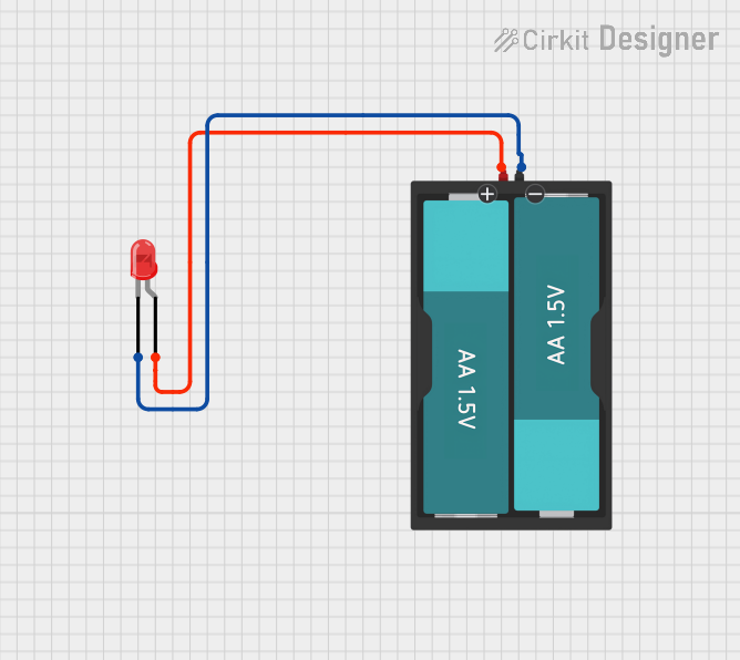
The circuit described by the provided inputs is a simple LED circuit powered by a 3V battery source. The circuit consists of a red two-pin LED and a battery holder for two AA batteries, providing a 3V supply. The LED has two terminals: an anode and a cathode. The anode is connected to the positive terminal of the battery (VCC), and the cathode is connected to the negative terminal of the battery (GND). This configuration allows current to flow through the LED when the battery is installed, causing the LED to emit light.
Component List
LED: Two Pin (red)
- Description: A basic red LED with two pins for connection.
- Pins:
cathode: Negative terminal of the LED.anode: Positive terminal of the LED.
- Purpose: To emit red light when powered by the battery.
Battery AAx2 3V
- Description: A battery holder designed to hold two AA batteries, providing a 3V output.
- Pins:
VCC: Positive terminal of the battery holder.GND: Negative terminal of the battery holder.
- Purpose: To provide the necessary power to the LED for it to function.
Wiring Details
LED: Two Pin (red)
- Cathode: Connected to the
GNDpin of the Battery AAx2 3V. - Anode: Connected to the
VCCpin of the Battery AAx2 3V.
Battery AAx2 3V
- VCC: Connected to the
anodepin of the LED: Two Pin (red). - GND: Connected to the
cathodepin of the LED: Two Pin (red).
Code Documentation
No microcontroller or embedded code is present in this circuit. Therefore, there is no code to document. The circuit operates purely on the electrical connections between the components.