Cirkit Designer
Your all-in-one circuit design IDE
Home /
Project Documentation
Arduino UNO and ESP32 CAM Controlled Robotic Vehicle with Bluetooth Interface

Circuit Documentation
Summary
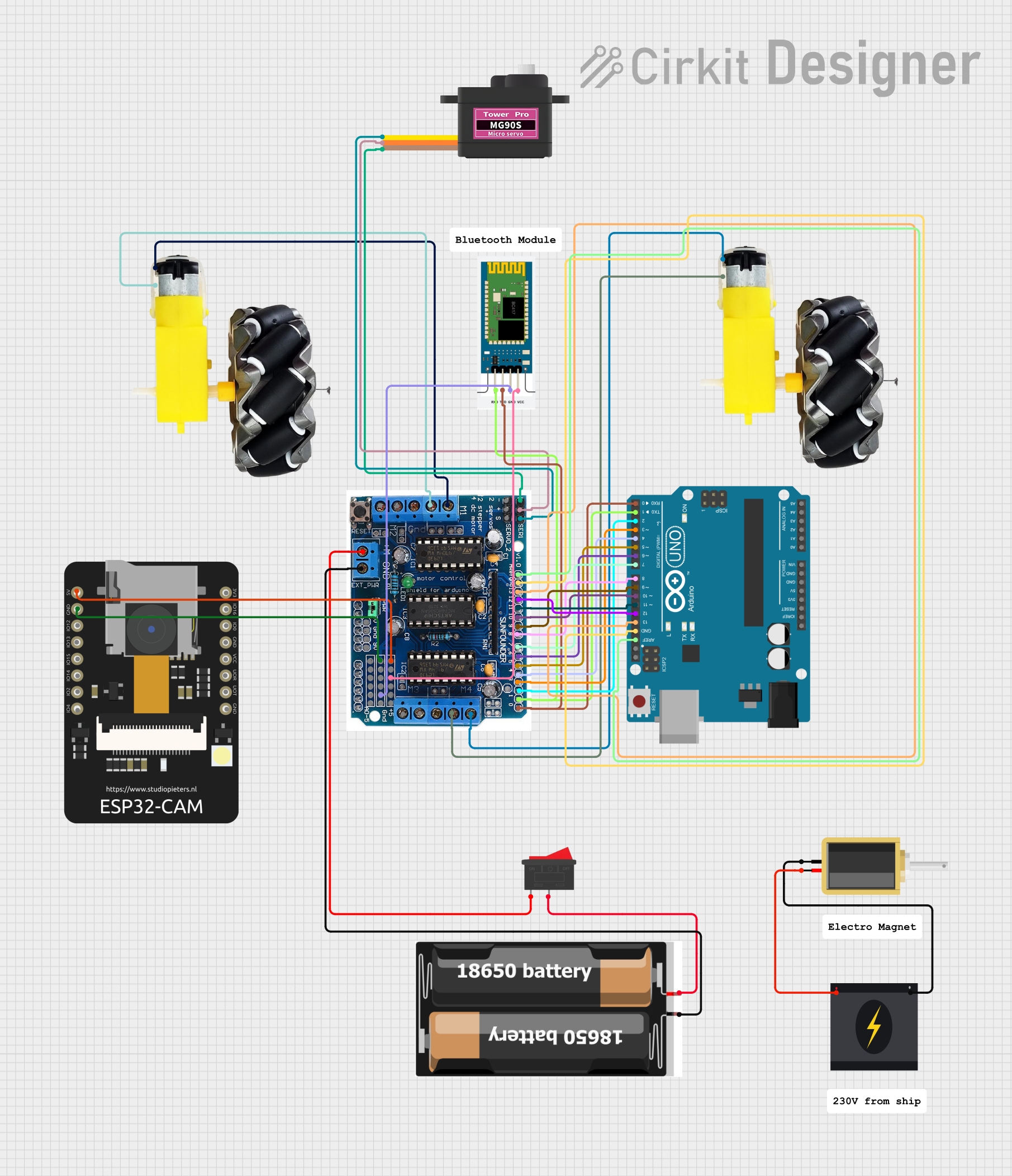
This circuit integrates various components to form a complex system capable of motor control, wireless communication, and power management. The core of the circuit is an Arduino UNO microcontroller, which interfaces with an L293D motor driver shield to control motors and wheels. Additionally, the circuit includes an ESP32 CAM for wireless camera functionality and an HC-06 Bluetooth module for wireless data communication. A servomotor (MG90S) is included for precise angular movement. Power management is handled by a rocker switch connected to a 2x 18650 battery pack, and a solenoid is driven by a 240V power source for actuation purposes.
Component List
- Arduino UNO: A microcontroller board based on the ATmega328P, featuring digital and analog I/O pins.
- L293D Motor Driver Shield: An expansion board for Arduino, designed to drive up to 4 DC motors or 2 stepper motors.
- Motor and Wheels: Two sets of DC motors with wheels, used for movement.
- Servomotor MG90S: A small and lightweight servomotor for precise control.
- ESP32 CAM: A small camera module with Wi-Fi capabilities.
- HC-06: A Bluetooth module for wireless data communication.
- Rocker Switch: A switch to control the power supply to the circuit.
- Solenoid: An electromagnetic actuator for switching or movement.
- 2x 18650 Battery Pack: A power source consisting of two 18650 lithium-ion batteries.
- 240V Power Source: A high-voltage power supply for the solenoid.
Wiring Details
Arduino UNO
- AREF connected to L293D Motor Driver Shield Aref
- GND connected to L293D Motor Driver Shield GND
- Digital pins D13 to D2 connected to corresponding pins 12 to 2 on L293D Motor Driver Shield
- Digital pin D1 (TX) connected to HC-06 RXD and L293D Motor Driver Shield pin 1
- Digital pin D0 (RX) connected to HC-06 TXD and L293D Motor Driver Shield pin 0
L293D Motor Driver Shield
- 5V connected to ESP32 CAM 5V and HC-06 VCC
- GND connected to ESP32 CAM GND and HC-06 GND
- M+ connected to Rocker Switch pin 1
- M1 connected to Motor and Wheels (instance 1) VCC and GND
- M4 connected to Motor and Wheels (instance 2) VCC and GND
- Servo1 connected to Servomotor MG90S SIG
- connected to Servomotor MG90S VCC
- connected to Servomotor MG90S GND
Motor and Wheels (Instance 1)
- VCC and GND connected to L293D Motor Driver Shield M1
Motor and Wheels (Instance 2)
- VCC and GND connected to L293D Motor Driver Shield M4
Servomotor MG90S
- SIG connected to L293D Motor Driver Shield Servo1
- VCC connected to L293D Motor Driver Shield +
- GND connected to L293D Motor Driver Shield -
ESP32 CAM
- 5V connected to L293D Motor Driver Shield 5V
- GND connected to L293D Motor Driver Shield GND
HC-06
- VCC connected to L293D Motor Driver Shield 5V
- GND connected to L293D Motor Driver Shield GND
- RXD connected to Arduino UNO D1 (TX)
- TXD connected to Arduino UNO D0 (RX)
Rocker Switch
- Pin 1 connected to L293D Motor Driver Shield M+
- Pin 2 connected to 2x 18650 Battery Pack VCC
2x 18650 Battery Pack
- VCC connected to Rocker Switch pin 2
- GND connected to L293D Motor Driver Shield GND
Solenoid
- Pin1 connected to 240V Power Source Neutral
- Pin2 connected to 240V Power Source Live
Documented Code
Arduino UNO Code (sketch.ino)
void setup() {
  // put your setup code here, to run once:

}

void loop() {
  // put your main code here, to run repeatedly:

}
Additional Notes
- The Arduino UNO code provided is a template with empty setup and loop functions. Actual functionality needs to be implemented based on the requirements of the circuit's operation.
- The HC-06 Bluetooth module is wired for serial communication with the Arduino UNO, allowing for wireless data transfer.
- The ESP32 CAM is powered by the 5V supply from the L293D Motor Driver Shield and shares a common ground.
- The servomotor is controlled via a dedicated servo pin on the motor driver shield, with power supplied directly from the shield.
- The solenoid is powered by a separate 240V source and is not controlled by the Arduino UNO in this configuration.
- The 2x 18650 battery pack provides power to the circuit through the rocker switch, allowing for an on/off mechanism.