
Dual DC Motor Control Circuit with Speed Regulation and Indicator Lamp
View and Edit Project In Cirkit Designer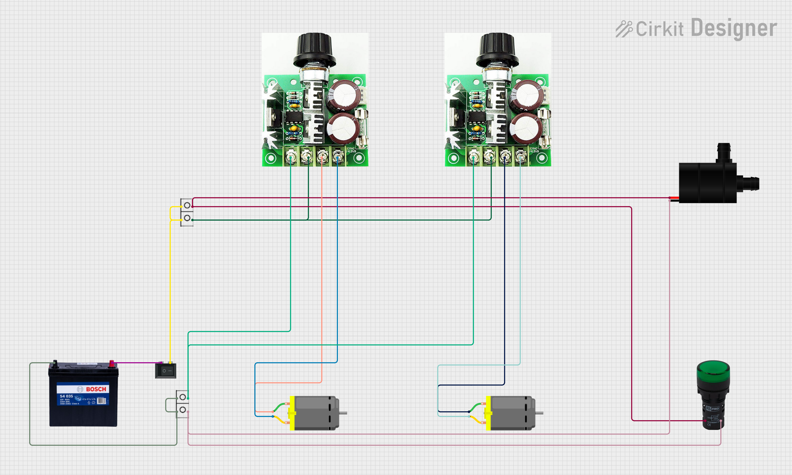
Circuit Documentation
Summary of the Circuit
This circuit is designed to control two DC motors using PWM (Pulse Width Modulation) speed controllers. It includes a 12V 200Ah battery as the power source, a water pump, two DC motors, two PWM motor speed controllers, a rocker switch to turn the circuit on and off, a pilot lamp to indicate when the circuit is active, and wire connectors to facilitate connections between components.
Component List
12V 200Ah Battery
- Description: A high-capacity battery that provides the main voltage supply for the circuit.
- Pins: GND, 12V
Water Pump
- Description: A pump powered by the circuit to move water through a system.
- Pins: VCC, GND
DC Motor
- Description: An electric motor that converts DC electrical energy into mechanical energy.
- Pins: pin 1, pin 2
12v~40v 10A PWM DC Motor Speed Controller
- Description: A controller that allows for speed control of a DC motor through PWM.
- Pins: GND, 0-5v, 5v, DC +, DC -, Motor +, Motor -
Rocker Switch (SPST)
- Description: A single-pole single-throw switch used to connect or disconnect power to the circuit.
- Pins: 1, 2
Pilot Lamp Green
- Description: An indicator light that illuminates when the circuit is powered.
- Pins: X1, X2
Wire Connector
- Description: A component used to join electrical terminations and create an electrical circuit.
- Pins: +, -
Wiring Details
12V 200Ah Battery
- GND connected to wire connector (-)
- 12V connected to Rocker Switch (SPST) pin 1
Water Pump
- VCC connected to wire connector (+) and Pilot Lamp Green (X1)
- GND connected to wire connector (-) and Pilot Lamp Green (X2)
DC Motor (First Instance)
- pin 1 connected to PWM DC Motor Speed Controller (DC -)
- pin 2 connected to PWM DC Motor Speed Controller (DC +)
DC Motor (Second Instance)
- pin 1 connected to PWM DC Motor Speed Controller (DC -)
- pin 2 connected to PWM DC Motor Speed Controller (DC +)
12v~40v 10A PWM DC Motor Speed Controller (First Instance)
- GND not connected
- 0-5v not connected
- 5v not connected
- DC + connected to DC Motor (pin 2)
- DC - connected to DC Motor (pin 1)
- Motor + connected to wire connector (-)
- Motor - connected to wire connector (+)
12v~40v 10A PWM DC Motor Speed Controller (Second Instance)
- GND not connected
- 0-5v not connected
- 5v not connected
- DC + connected to DC Motor (pin 2)
- DC - connected to DC Motor (pin 1)
- Motor + connected to wire connector (-)
- Motor - connected to wire connector (+)
Rocker Switch (SPST)
- 1 connected to 12V 200Ah Battery (12V)
- 2 connected to wire connector (+)
Pilot Lamp Green
- X1 connected to Water Pump (VCC)
- X2 connected to Water Pump (GND)
Wire Connector (First Instance)
- + connected to 12V 200Ah Battery (GND), DC Motor Speed Controller (Motor -), and Pilot Lamp Green (X2)
- - connected to 12V 200Ah Battery (GND), DC Motor Speed Controller (Motor +), and Pilot Lamp Green (X1)
Wire Connector (Second Instance)
- + connected to Rocker Switch (SPST) pin 2
- - connected to Rocker Switch (SPST) pin 2
Documented Code
There is no code provided for any microcontrollers in this circuit. If there were microcontrollers involved, this section would include the code along with explanations for each part of the code, including setup, main loop, and any functions or interrupts used to control the circuit's behavior.