
Sound-Activated LED Lighting with ESP32 and INMP441 Microphone
View and Edit Project In Cirkit Designer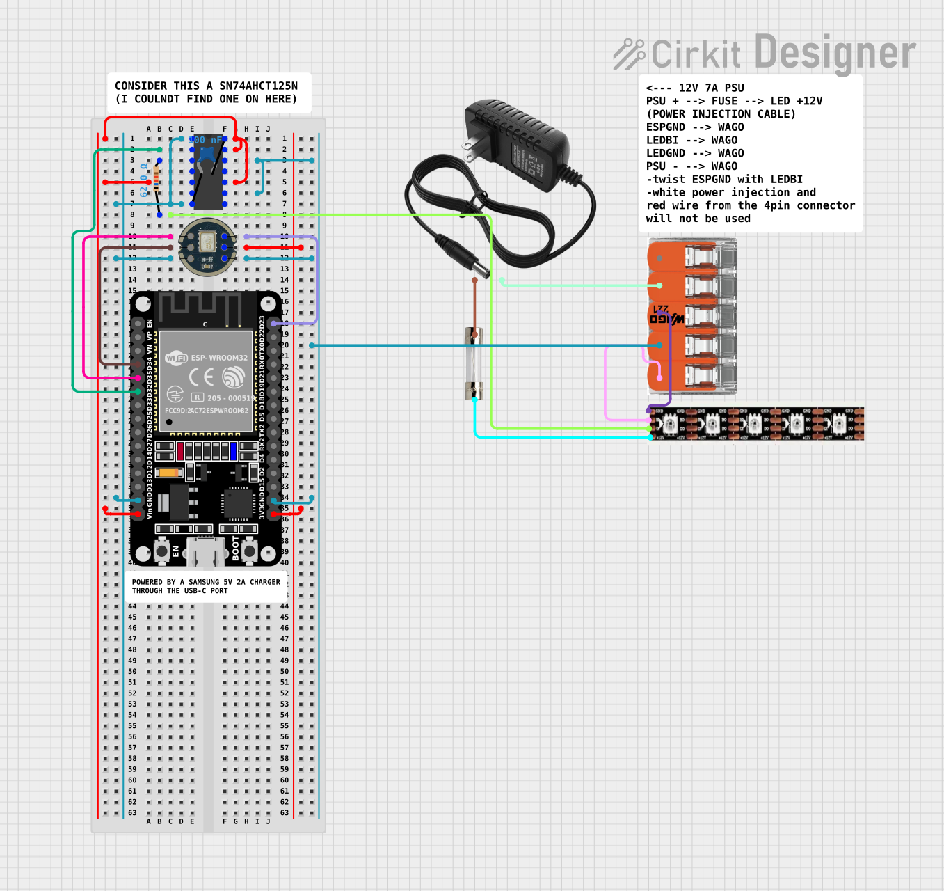
Circuit Documentation
Summary
This circuit is designed to interface an ESP32 microcontroller with various components including an SN74AHC14 hex inverter, a ceramic capacitor, a resistor, an INMP441 microphone module, a WS2815 LED strip, and a 5A fuse for protection. The circuit is powered by a 12V power supply. The ESP32 is used to control the LED strip and to process signals from the INMP441 microphone module. The SN74AHC14 provides signal conditioning with its Schmitt-trigger inputs.
Component List
12V Power Supply
- Provides the main voltage source for the circuit.
SN74AHC14 Hex Inverter
- A hex inverter with Schmitt-trigger inputs used for signal conditioning.
Ceramic Capacitor
- A 0.1 µF capacitor, likely used for decoupling purposes.
Resistor
- A 62 Ohm resistor, possibly used for current limiting or pull-up/pull-down purposes.
ESP32 (30 pin)
- A microcontroller with Wi-Fi and Bluetooth capabilities, used as the main processing unit in the circuit.
INMP441 Microphone Module
- A digital I2S output microphone module for audio input.
WS2815 LED Strip
- An addressable LED strip that operates at 12V and is controlled via a digital signal.
5A Fuse
- Provides overcurrent protection for the circuit.
Splicing Connector WAGO 221
- A connector used for joining multiple wires together.
Wiring Details
12V Power Supply
+connected to the input of the 5A fuse.-connected to Port 2 of the Splicing connector WAGO 221.
SN74AHC14 Hex Inverter
Vccconnected to the Vin pin of the ESP32, Ceramic Capacitor pin1, and SN74AHC14 pins 6A, 5Y, 3A.GNDconnected to the GND pin of the ESP32, Ceramic Capacitor pin0, and SN74AHC14 pin 1A.1Yconnected to the D32 pin of the ESP32.6Yconnected to the GND pin of the INMP441, Port 4 of the Splicing connector WAGO 221, and GND pin of the ESP32.2Aconnected to one pin of the Resistor.
Ceramic Capacitor
pin0connected to GND of the SN74AHC14 and GND pin of the ESP32.pin1connected to Vcc of the SN74AHC14 and Vin pin of the ESP32.
Resistor
pin1connected to the D0 pin of the WS2815 LED Strip.pin2connected to the 2A pin of the SN74AHC14.
ESP32 (30 pin)
GNDconnected to GND of the SN74AHC14, GND of the INMP441, and Port 4 of the Splicing connector WAGO 221.Vinconnected to Vcc of the SN74AHC14 and pin1 of the Ceramic Capacitor.D32connected to 1Y of the SN74AHC14.D35not connected to any other components in the provided net list.D23connected to the SD pin of the INMP441.3V3connected to the VDD pin of the INMP441.
INMP441 Microphone Module
GNDconnected to 6Y of the SN74AHC14, Port 4 of the Splicing connector WAGO 221, and GND pin of the ESP32.VDDconnected to the 3V3 pin of the ESP32.SDconnected to the D23 pin of the ESP32.
WS2815 LED Strip
GNDconnected to Port 3 of the Splicing connector WAGO 221.B0connected to Port 5 of the Splicing connector WAGO 221.D0connected to pin1 of the Resistor.+12Vconnected to the output of the 5A fuse.
5A Fuse
inputconnected to the+of the 12V power supply.outputconnected to the+12Vof the WS2815 LED Strip.
Splicing Connector WAGO 221
Port 2connected to the-of the 12V power supply.Port 3connected to the GND of the WS2815 LED Strip.Port 4connected to the 6Y of the SN74AHC14, GND of the INMP441, and GND pin of the ESP32.Port 5connected to the B0 of the WS2815 LED Strip.
Documented Code
SN74AHC14 Hex Inverter
void setup() {
  // put your setup code here, to run once:

}

void loop() {
  // put your main code here, to run repeatedly:

}
Note: The provided code for the SN74AHC14 is a template and does not contain any functional code specific to the SN74AHC14, as it is not a programmable device.
ESP32 (30 pin)
No code provided for the ESP32 microcontroller. It is assumed that the user will write the necessary code to control the LED strip and process the microphone input.