
Arduino Nano-Based Wireless Load Cell and Environmental Sensor System
View and Edit Project In Cirkit Designer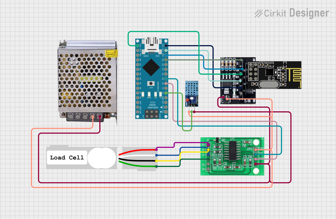
Circuit Documentation
Summary
This document provides a detailed overview of a circuit that includes an Arduino Nano, a load cell, an HX711 bridge sensor interface, an NRF24L01 wireless module with an adapter, a DHT11 temperature and humidity sensor, and a 5V power supply. The circuit is designed to measure weight using the load cell, transmit data wirelessly using the NRF24L01 module, and monitor environmental conditions using the DHT11 sensor.
Component List
POWER SUPPLY 5V 5AMP
- Description: Provides 5V DC power to the circuit.
- Pins:
- 220V Positive Pole (AC)
- 220V Negative Pole (AC)
- GND
- GND (DC)
- 12V-24V Output (DC)
Arduino Nano
- Description: A small, complete, and breadboard-friendly board based on the ATmega328P.
- Pins:
- D1/TX
- D0/RX
- RESET
- GND
- D2
- D3
- D4
- D5
- D6
- D7
- D8
- D9
- D10
- D11/MOSI
- D12/MISO
- VIN
- 5V
- A7
- A6
- A5
- A4
- A3
- A2
- A1
- A0
- AREF
- 3V3
- D13/SCK
Load Cell - Red/white/black/green
- Description: A sensor used to measure weight.
- Pins:
- E+
- A-
- E-
- A+
NRF24L01 Adapter
- Description: Adapter for the NRF24L01 wireless module.
- Pins:
- CE
- CSN
- SCK
- MOSI
- MISO
- IRQ
- VCC
- GND
NRF24L01
- Description: A wireless transceiver module.
- Pins:
- IRQ (not used)
- MOSI
- CSN
- VCC (3V)
- GND
- CE
- SCK
- MISO
DHT 11
- Description: A temperature and humidity sensor.
- Pins:
- VCC
- GND
- DATA
HX711 - Bridge Sensor Interface
- Description: An interface for bridge sensors like load cells.
- Pins:
- E+
- E-
- A-
- A+
- B-
- B+
- GND - GROUND
- DATA (OUT)
- SCK - CLOCK (IN)
- 3.3/3.5V Supply
Wiring Details
POWER SUPPLY 5V 5AMP
GND (DC) is connected to:
- HX711 - Bridge Sensor Interface: GND - GROUND
- DHT 11: GND
- NRF24L01 Adapter: GND
12V-24V Output (DC) is connected to:
- HX711 - Bridge Sensor Interface: 3.3/3.5V Supply
- DHT 11: VCC
- NRF24L01 Adapter: VCC
Arduino Nano
D2 is connected to:
- DHT 11: DATA
D4 is connected to:
- HX711 - Bridge Sensor Interface: SCK - CLOCK (IN)
D5 is connected to:
- HX711 - Bridge Sensor Interface: DATA (OUT)
D9 is connected to:
- NRF24L01 Adapter: CE
D10 is connected to:
- NRF24L01 Adapter: CSN
D11/MOSI is connected to:
- NRF24L01 Adapter: MOSI
D12/MISO is connected to:
- NRF24L01 Adapter: MISO
D13/SCK is connected to:
- NRF24L01 Adapter: SCK
Load Cell - Red/white/black/green
E+ is connected to:
- HX711 - Bridge Sensor Interface: E+
A- is connected to:
- HX711 - Bridge Sensor Interface: A-
E- is connected to:
- HX711 - Bridge Sensor Interface: E-
A+ is connected to:
- HX711 - Bridge Sensor Interface: A+
NRF24L01 Adapter
CE is connected to:
- Arduino Nano: D9
CSN is connected to:
- Arduino Nano: D10
MOSI is connected to:
- Arduino Nano: D11/MOSI
MISO is connected to:
- Arduino Nano: D12/MISO
SCK is connected to:
- Arduino Nano: D13/SCK
VCC is connected to:
- POWER SUPPLY 5V 5AMP: 12V-24V Output (DC)
GND is connected to:
- POWER SUPPLY 5V 5AMP: GND (DC)
DHT 11
VCC is connected to:
- POWER SUPPLY 5V 5AMP: 12V-24V Output (DC)
GND is connected to:
- POWER SUPPLY 5V 5AMP: GND (DC)
DATA is connected to:
- Arduino Nano: D2
HX711 - Bridge Sensor Interface
E+ is connected to:
- Load Cell - Red/white/black/green: E+
A- is connected to:
- Load Cell - Red/white/black/green: A-
E- is connected to:
- Load Cell - Red/white/black/green: E-
A+ is connected to:
- Load Cell - Red/white/black/green: A+
GND - GROUND is connected to:
- POWER SUPPLY 5V 5AMP: GND (DC)
DATA (OUT) is connected to:
- Arduino Nano: D5
SCK - CLOCK (IN) is connected to:
- Arduino Nano: D4
3.3/3.5V Supply is connected to:
- POWER SUPPLY 5V 5AMP: 12V-24V Output (DC)
Documented Code
Arduino Nano Code (sketch.ino)
void setup() {
  // put your setup code here, to run once:

}

void loop() {
  // put your main code here, to run repeatedly:

}
Additional Documentation (documentation.txt)