
Dual-Microcontroller Audio Processing System with Visual Indicators and Battery Management
View and Edit Project In Cirkit Designer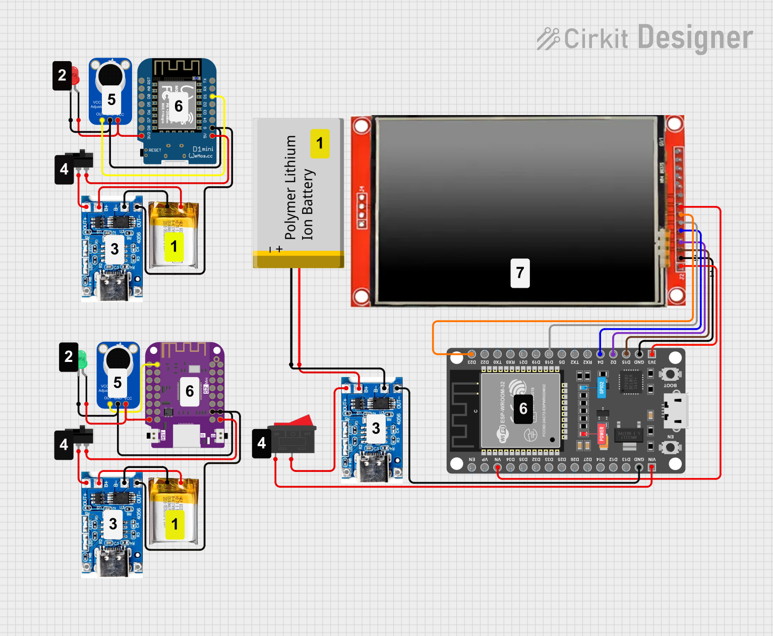
Circuit Documentation
Summary
This document provides a detailed overview of a circuit designed to interface various components including microcontrollers, a microphone amplifier, LEDs, switches, a battery charging module, and a TFT LCD screen. The circuit is powered by 3.7v LiPo batteries and includes charging modules for battery management. The Wemos S2 Mini and Wemos D1 Mini microcontrollers serve as the central processing units, interfacing with the microphone amplifiers and LEDs. The ESP 32 DEVKIT V1 microcontroller drives the LCD TFT screen ILI9488 HD. Toggle and rocker switches are used to control power flow within the circuit.
Component List
Microcontrollers
- Wemos D1 Mini: A compact microcontroller based on the ESP-8266EX.
- Wemos S2 Mini: A small form-factor microcontroller featuring the ESP32-S2FN4R2 chip.
- ESP 32 DEVKIT V1 (30 pins): A development board with an ESP32 chip, suitable for various IoT applications.
Sensors and Modules
- Adafruit MAX4466 Electret Microphone Amplifier: An amplifier module designed for use with electret microphones, providing adjustable gain.
Power Components
- 3.7v LiPo Battery: A rechargeable lithium polymer battery providing a power source for the circuit.
- TP4056 Battery Charging Protection Module (Type C): A module for charging lithium batteries and providing protection against overcharging.
Display
- LCD TFT screen ILI9488 HD: A color display with a resolution suitable for graphics and text.
Indicators
- LED: Two Pin (green): A green LED used as an indicator light.
- LED: Two Pin (red): A red LED used as an indicator light.
Switches
- Toggle Switch: A switch that can connect or disconnect the circuit, changing the state between on and off.
- Rocker Switch: A type of on/off switch that rocks when pressed.
Wiring Details
Wemos S2 Mini
3.3Vconnected to Adafruit MAX4466 Electret Microphone Amplifier (VCC) and LED (green, anode).GPIO 1connected to Adafruit MAX4466 Electret Microphone Amplifier (OUT).VBUSconnected to Toggle Switch (L2).GNDconnected to Adafruit MAX4466 Electret Microphone Amplifier (GND) and LED (green, cathode).GNDconnected to TP4056 Battery Charging Protection Module (OUT -).
Wemos D1 Mini
3V3connected to Adafruit MAX4466 Electret Microphone Amplifier (VCC) and LED (red, anode).5Vconnected to Toggle Switch (L2).Gconnected to Adafruit MAX4466 Electret Microphone Amplifier (GND), TP4056 Battery Charging Protection Module (OUT -), and LED (red, cathode).D1connected to Adafruit MAX4466 Electret Microphone Amplifier (OUT).
ESP 32 DEVKIT V1 (30 pins)
VNconnected to LCD TFT screen ILI9488 HD (BL).GNDconnected to TP4056 Battery Charging Protection Module (OUT -) and LCD TFT screen ILI9488 HD (GND).VINconnected to Rocker Switch (1).3V3connected to LCD TFT screen ILI9488 HD (VCC (3.3~5V)).D15connected to LCD TFT screen ILI9488 HD (CS).D2connected to LCD TFT screen ILI9488 HD (RST).D4connected to LCD TFT screen ILI9488 HD (D/C).D18connected to LCD TFT screen ILI9488 HD (SDI(MOSI)).D23connected to LCD TFT screen ILI9488 HD (SCK).
Adafruit MAX4466 Electret Microphone Amplifier
VCCconnected to Wemos S2 Mini (3.3V) and Wemos D1 Mini (3V3).GNDconnected to Wemos S2 Mini (GND), Wemos D1 Mini (G), and TP4056 Battery Charging Protection Module (OUT -).OUTconnected to Wemos S2 Mini (GPIO 1) and Wemos D1 Mini (D1).
TP4056 Battery Charging Protection Module (Type C)
OUT +connected to Toggle Switch (COM) and Rocker Switch (2).B+connected to 3.7v LiPo Battery (+Ve).B-connected to 3.7v LiPo Battery (GND).OUT -connected to Wemos S2 Mini (GND), Wemos D1 Mini (G), and Adafruit MAX4466 Electret Microphone Amplifier (GND).
LED: Two Pin (green)
anodeconnected to Wemos S2 Mini (3.3V).cathodeconnected to Wemos S2 Mini (GND).
LED: Two Pin (red)
anodeconnected to Wemos D1 Mini (3V3).cathodeconnected to Wemos D1 Mini (G).
Toggle Switch
L2connected to Wemos S2 Mini (VBUS) and Wemos D1 Mini (5V).COMconnected to TP4056 Battery Charging Protection Module (OUT +).
Rocker Switch
1connected to ESP 32 DEVKIT V1 (VIN).2connected to TP4056 Battery Charging Protection Module (OUT +).
LCD TFT screen ILI9488 HD
VCC (3.3~5V)connected to ESP 32 DEVKIT V1 (3V3).GNDconnected to ESP 32 DEVKIT V1 (GND).CSconnected to ESP 32 DEVKIT V1 (D15).RSTconnected to ESP 32 DEVKIT V1 (D2).D/Cconnected to ESP 32 DEVKIT V1 (D4).SDI(MOSI)connected to ESP 32 DEVKIT V1 (D18).SCKconnected to ESP 32 DEVKIT V1 (D23).BLconnected to ESP 32 DEVKIT V1 (VN).
Documented Code
No code has been provided for the microcontrollers in the circuit. If code is available, it should be documented here with appropriate comments and explanations for each section of the code.