
Circuit Documentation
Summary of the Circuit
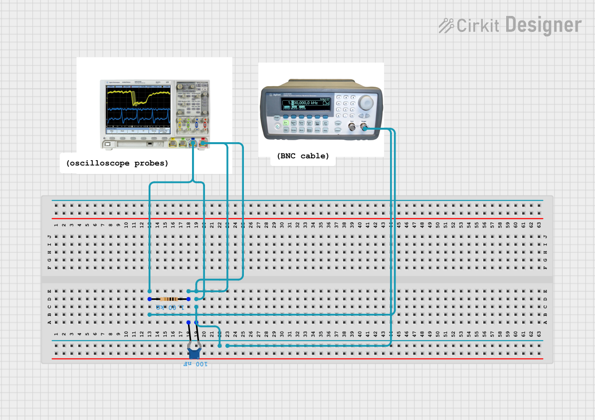
The circuit described by the provided inputs appears to be a simple test setup that includes a Mixed Signal Oscilloscope, a Function Generator, a Resistor, and a Ceramic Capacitor. The Function Generator is likely used to provide a test signal, which is then passed through the Resistor and Ceramic Capacitor before being measured by the Mixed Signal Oscilloscope. This setup could be used for a variety of purposes, such as analyzing the frequency response of the resistor-capacitor (RC) network or for educational demonstrations of basic electronic principles.
Component List
Mixed Signal Oscilloscope
- Description: A device used to measure and analyze electrical signals.
- Pins: 4 pins available for connections.
Function Generator
- Description: A device that generates various types of electrical waveforms over a wide range of frequencies.
- Pins:
sync,Output
Resistor
- Description: A passive electrical component that provides resistance to the flow of electric current.
- Resistance: 1000 Ohms
Ceramic Capacitor
- Description: A passive electrical component that stores energy in the form of an electric field.
- Capacitance: 0.1 µF (microfarads)
Wiring Details
Mixed Signal Oscilloscope
- Pin 3: Connected to the Ceramic Capacitor pin 0.
- Pin 4: Connected to the Ceramic Capacitor pin 1.
Function Generator
- Output: Connected to the Mixed Signal Oscilloscope pin 3 and pin 4 through the RC network.
Resistor
- Pin 1: Connected to the Ceramic Capacitor pin 1.
- Pin 2: Connected to the Ceramic Capacitor pin 0.
Ceramic Capacitor
- Pin 0: Connected to the Mixed Signal Oscilloscope pin 3 and Resistor pin 2.
- Pin 1: Connected to the Mixed Signal Oscilloscope pin 4 and Resistor pin 1.
Documented Code
No code has been provided for any microcontrollers in the circuit. Therefore, there is no embedded code to document at this time.
This documentation provides an overview of the circuit components and their connections. For further details or specific use cases, additional information would be required.