Arduino Mega 2560 Based Environmental and Position Tracking System
Circuit Documentation
Summary
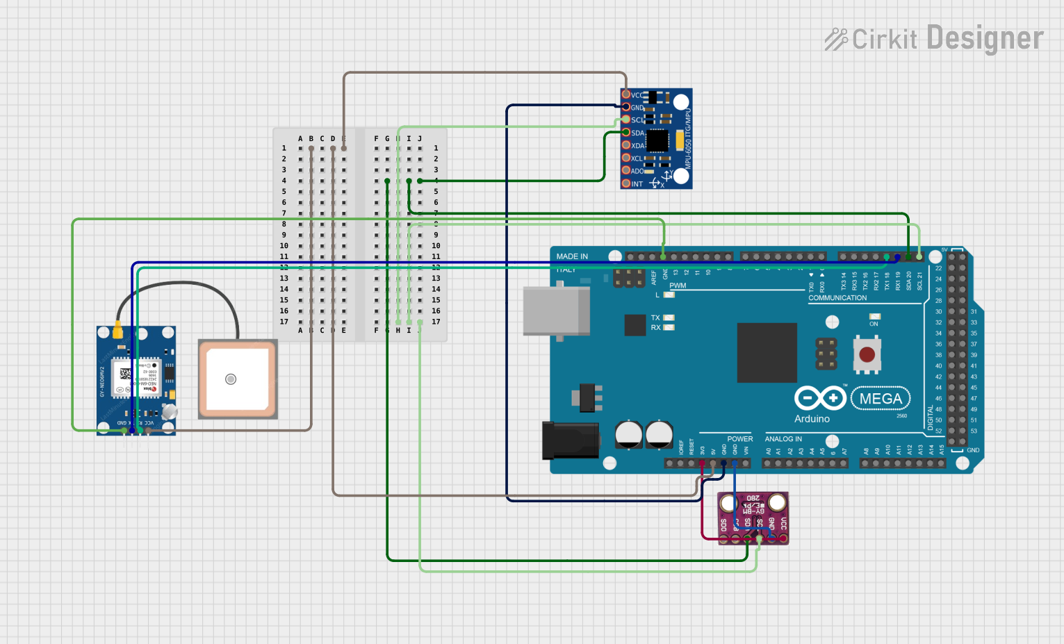
This circuit is designed to interface an Arduino Mega 2560 with a BMP280 barometric pressure sensor, an MPU-6050 accelerometer/gyroscope, and a GPS NEO 6M module. The Arduino Mega 2560 serves as the central processing unit, collecting data from the sensors and providing output through its serial interface. The BMP280 and MPU-6050 are connected via the I2C bus, while the GPS NEO 6M module communicates with the Arduino through a serial connection.
Component List
Arduino Mega 2560
- Description: A microcontroller board based on the ATmega2560.
- Purpose: Acts as the central processing unit for the circuit, interfacing with sensors and handling data processing and communication.
BMP280
- Description: A barometric pressure sensor that can also measure temperature.
- Purpose: Provides atmospheric pressure and temperature readings to the Arduino.
MPU-6050
- Description: A motion tracking device that contains a 3-axis accelerometer and a 3-axis gyroscope.
- Purpose: Measures acceleration and angular rates, providing motion sensing data to the Arduino.
GPS NEO 6M
- Description: A GPS module capable of providing location, speed, and time information.
- Purpose: Supplies the Arduino with geographical positioning data.
Wiring Details
Arduino Mega 2560
- I2C Connection:
D20/SDAconnected to SDA pins of BMP280 and MPU-6050.D21/SCLconnected to SCL pins of BMP280 and MPU-6050.
- Power:
3V3connected to VCC of BMP280.5Vconnected to VCC of MPU-6050 and GPS NEO 6M.GNDconnected to GND pins of BMP280, MPU-6050, and GPS NEO 6M.
- Serial Connection:
D19/RX1connected to TX of GPS NEO 6M.D18/TX1connected to RX of GPS NEO 6M.
BMP280
- I2C Connection:
SDAconnected toD20/SDAon Arduino Mega 2560.SCLconnected toD21/SCLon Arduino Mega 2560.
- Power:
VCCconnected to3V3on Arduino Mega 2560.GNDconnected toGNDon Arduino Mega 2560.
MPU-6050
- I2C Connection:
SDAconnected toD20/SDAon Arduino Mega 2560.SCLconnected toD21/SCLon Arduino Mega 2560.
- Power:
VCCconnected to5Von Arduino Mega 2560.GNDconnected toGNDon Arduino Mega 2560.
GPS NEO 6M
- Serial Connection:
RXconnected toD18/TX1on Arduino Mega 2560.TXconnected toD19/RX1on Arduino Mega 2560.
- Power:
VCCconnected to5Von Arduino Mega 2560.GNDconnected toGNDon Arduino Mega 2560.
Documented Code
#include <Wire.h>
#include <Adafruit_Sensor.h>
#include <Adafruit_BMP280.h>
#include <MPU6050.h>
#include <TinyGPS++.h>
#include <SoftwareSerial.h>

// Create instances of the sensor libraries
Adafruit_BMP280 bmp; // I2C
MPU6050 mpu;
TinyGPSPlus gps;
SoftwareSerial gpsSerial(4, 3); // RX, TX

void setup() {
  // Initialize serial communication
  Serial.begin(115200);
  gpsSerial.begin(9600);

  // Initialize BMP280
  if (!bmp.begin(0x76)) { // BMP280 I2C address is 0x76 or 0x77
    Serial.println(F("Could not find a valid BMP280 sensor, check wiring!"));
    while (1);
  }
  Serial.println(F("BMP280 initialized"));

  // Initialize MPU6050
  Wire.begin();
  mpu.initialize();
  if (!mpu.testConnection()) {
    Serial.println(F("MPU6050 connection failed"));
    while (1);
  }
  Serial.println(F("MPU6050 initialized"));

  // Initialize GPS
  Serial.println(F("GPS module initialized"));
}

void loop() {
  // Read data from BMP280
  float temperature = bmp.readTemperature();
  float pressure = bmp.readPressure();
  Serial.print(F("Temperature = "));
  Serial.print(temperature);
  Serial.println(F(" *C"));
  Serial.print(F("Pressure = "));
  Serial.print(pressure / 100.0F);
  Serial.println(F(" hPa"));

  // Read data from MPU6050
  int16_t ax, ay, az;
  int16_t gx, gy, gz;
  mpu.getAcceleration(&ax, &ay, &az);
  mpu.getRotation(&gx, &gy, &gz);

  // Convert to g and degrees/s
  float ax_g = ax / 16384.0;  // Scale factor for accelerometer
  float ay_g = ay / 16384.0;  // Scale factor for accelerometer
  float az_g = az / 16384.0;  // Scale factor for accelerometer

  float gx_dps = gx / 131.0;  // Scale factor for gyroscope
  float gy_dps = gy / 131.0;  // Scale factor for gyroscope
  float gz_dps = gz / 131.0;  // Scale factor for gyroscope

  Serial.print(F("Accel X = "));
  Serial.print(ax_g);
  Serial.print(F(", Y = "));
  Serial.print(ay_g);
  Serial.print(F(", Z = "));
  Serial.println(az_g);

  Serial.print(F("Gyro X = "));
  Serial.print(gx_dps);
  Serial.print(F(", Y = "));
  Serial.print(gy_dps);
  Serial.print(F(", Z = "));
  Serial.println(gz_dps);

  // Read data from GPS
  while (gpsSerial.available() > 0) {
    gps.encode(gpsSerial.read());
    if (gps.location.isUpdated()) {
      Serial.print(F("Latitude= "));
      Serial.print(gps.location.lat(), 6);
      Serial.print(F(", Longitude= "));
      Serial.print(gps.location.lng(), 6);
      Serial.print(F(", Altitude= "));
      Serial.print(gps.altitude.meters());
      Serial.println(F(" meters"));
    }
  }

  delay(1000); // Delay 1 second between readings
}
This code initializes the sensors connected to the Arduino Mega 2560 and reads data from them in a continuous loop. The BMP280 sensor provides temperature and pressure readings, the MPU-6050 provides acceleration and gyroscope data, and the GPS NEO 6M provides location data. The data is printed to the serial monitor for observation.