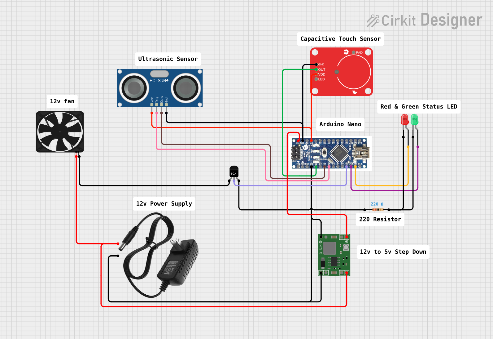
Arduino-Controlled Ultrasonic Distance Measurement with Fan Speed Regulation and Touch-Activated LED Indicators

Circuit Documentation
Summary
This circuit is designed to control a fan and a set of LEDs (red and green) based on input from a capacitive touch sensor and an HC-SR04 ultrasonic sensor. The Arduino Nano serves as the central microcontroller, processing sensor inputs and controlling the output devices accordingly. The circuit includes a power supply system that utilizes a 12v power supply and an MP1584EN power regulator board to provide the necessary voltages to the components. An NPN transistor is used to switch the fan on and off, and a resistor is included to limit current to the LEDs.
Component List
LEDs
- LED (Red): A two-pin red LED that indicates status or provides a visual alert.
- LED (Green): A two-pin green LED that indicates status or provides a visual alert.
Sensors and Input Devices
- Capacitive Touch Breakout: An input device that detects touch or proximity.
- HC-SR04 Ultrasonic Sensor: A sensor that measures distance using ultrasonic waves.
Power Components
- 12v Power Supply: Provides the main power source for the circuit.
- MP1584EN Power Regulator Board: Steps down the voltage from the power supply to a lower level suitable for the Arduino and other components.
Control Components
- Arduino Nano: The microcontroller unit that runs the embedded code to control the circuit.
- NPN-Transistor: Acts as a switch to control the power to the fan.
Passive Components
- Resistor (220 Ohms): Limits the current to the LEDs to prevent damage.
Output Devices
- Fan: An output device that is controlled based on sensor inputs.
Wiring Details
LEDs
LED (Red)
- Cathode connected to a common resistor.
- Anode connected to Arduino Nano pin D11.
LED (Green)
- Cathode connected to the same common resistor as the red LED.
- Anode connected to Arduino Nano pin D10.
Sensors and Input Devices
Capacitive Touch Breakout
- GND connected to the common ground.
- VDD connected to the 5V supply from the Arduino Nano.
- OUT connected to Arduino Nano pin D2.
HC-SR04 Ultrasonic Sensor
- GND connected to the common ground.
- VCC connected to the 5V supply from the Arduino Nano.
- TRIG connected to Arduino Nano pin D5.
- ECHO connected to Arduino Nano pin D4.
Power Components
12v Power Supply
- "+" connected to the input of the MP1584EN Power Regulator Board and the Fan.
- "-" connected to the common ground.
MP1584EN Power Regulator Board
- IN+ and IN- connected to the 12v power supply.
- OUT+ connected to the Arduino Nano VIN pin.
- OUT- connected to the common ground.
Control Components
- NPN-Transistor
- Emitter (E) connected to the Fan GND.
- Collector (C) connected to Arduino Nano pin D9.
- Base (B) connected to the common ground through a resistor.
Passive Components
- Resistor (220 Ohms)
- One pin connected to the cathodes of both the red and green LEDs.
- The other pin connected to the common ground.
Output Devices
- Fan
- GND connected to the emitter of the NPN transistor.
- 5V connected to the 12v power supply.
Documented Code
#include <Wire.h>

const int trigPin = 5;
const int echoPin = 4;
const int fanSignal = 9;
const int button = 2;
float distance , duration;
const int greenLED = 10;
const int redLED = 11;
bool startSeq = false;
bool buttonState = false;
bool prevButtonState = false;
unsigned int lastDebounceTime;
const int debounceDelay = 30;

void setup() {
  Serial.begin(9600);
  pinMode(trigPin, OUTPUT);
  pinMode(echoPin, INPUT);
  pinMode(fanSignal, OUTPUT);
  pinMode(greenLED, OUTPUT);
  pinMode(redLED, OUTPUT);
  pinMode(button, INPUT);
  digitalWrite(redLED, HIGH); // Assuming redLED is the yellow LED (ledy)
  delay(2000);
}

void loop() {
  // Read the state of the button
  int currentButtonState = digitalRead(button);

  // Check if the button state has changed
  if (currentButtonState != prevButtonState) {
    // Reset the debouncing timer
    lastDebounceTime = millis();
  }

  // If the current time is greater than the last debounce time plus the debounce delay, proceed
  if ((millis() - lastDebounceTime) > debounceDelay) {
    // If the button state has changed and is LOW (pressed)
    if (currentButtonState == LOW && prevButtonState == HIGH) {
      Serial.println("Button pressed");
      digitalWrite(greenLED, LOW);
      startSeq = !startSeq;
      analogWrite(fanSignal, 0);
    }
  }

  // Save the current state as the last state, for next time through the loop
  prevButtonState = currentButtonState;

  if (startSeq) {
    digitalWrite(redLED, LOW);
    delay(100);
    digitalWrite(trigPin, LOW);
    delayMicroseconds(2);
    digitalWrite(trigPin, HIGH);
    delayMicroseconds(10);
    digitalWrite(trigPin, LOW);
    duration = pulseIn(echoPin, HIGH);
    distance = (duration * .0343) / 2;
    Serial.print("Distance: ");
    Serial.println(distance);
    Control(distance);
    fanstatus();
    delay(500);
  }
}

// Fan Operating controller
void Control(float distance) {
  float x;
  if (distance >= 50.00) {
    x = 50;
  } else {
    x = distance;
  }
  float fanSpeed = map(x, 0, 50, 135, 255);
  // map variable y from 0-50 to 127-255 pwm range values
  analogWrite(fanSignal, fanSpeed);
  Serial.println(fanSpeed);
  unsigned int fanSpeedPercent = map(fanSpeed, 140, 255, 1, 99);
  Serial.println(fanSpeedPercent);
  delay(100);
}

// Function for Green LED "ON"
void fanstatus() {
  Serial.println("Fan: On");
  digitalWrite(greenLED, HIGH);
}
This code is designed to run on an Arduino Nano and controls the fan speed and LED states based on the distance measured by the ultrasonic sensor and the state of the capacitive touch sensor. The red LED is turned on at the start and then controlled by the touch sensor. The fan's speed is adjusted according to the distance measured, and the green LED indicates when the fan is on. The button's state is debounced to ensure stable operation.