ESP8266 Nodemcu Controlled EV Wireless Charging System
Circuit Documentation
Summary
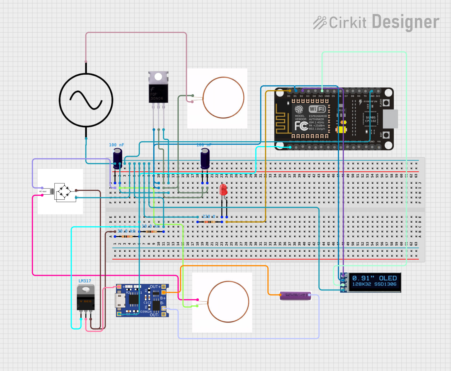
The circuit in question appears to be a wireless charging system with voltage regulation and battery charging capabilities. It includes an AC power supply, a bridge rectifier for converting AC to DC, a voltage regulator for maintaining a stable output voltage, and a charging module for a 3.7V battery. The system is controlled by an ESP8266 NodeMCU microcontroller, which manages the charging process and provides user feedback through an OLED display. The circuit also includes a MOSFET for switching purposes, resistors for current limiting, and capacitors for voltage smoothing.
Component List
Mosfet
- Description: A three-terminal device used for switching and amplifying electronic signals.
- Pins: Gate, Drain, Source
Copper Coil
- Description: A component used in creating magnetic fields or inductance.
- Pins: -ve, +ve
AC Supply
- Description: A source of alternating current (AC) electricity.
- Pins: +ve, -ve
ESP8266 NodeMCU
- Description: A Wi-Fi enabled microcontroller for IoT applications.
- Pins: D0, D1, D2, D3, D4, 3V3, GND, D5, D6, D7, D8, RX, TX, A0, RSV, SD3, SD2, SD1, CMD, SD0, CLK, EN, RST, VIN
Electrolytic Capacitor
- Description: A polarized capacitor with a larger capacitance per unit volume.
- Pins: -, +
- Properties: Capacitance: 1e-7 Farads
Bridge Rectifier
- Description: A circuit that converts alternating current (AC) to direct current (DC).
- Pins: AC input +, AC input -, +, -
LM317 Voltage Regulator
- Description: An adjustable voltage regulator capable of supplying more than 1.5A over an output voltage range of 1.25V to 37V.
- Pins: Adj, V_out, V_in
TP4056
- Description: A complete constant-current/constant-voltage linear charger for single-cell lithium-ion batteries.
- Pins: OUT-, B-, B+, OUT+, IN-, IN+
3.7V Battery
- Description: A rechargeable lithium-ion battery.
- Pins: +, -
Resistor
- Description: A passive two-terminal electrical component that implements electrical resistance as a circuit element.
- Pins: pin1, pin2
- Properties: Various resistance values (30kΩ, 10kΩ, 220Ω)
LED: Two Pin (red)
- Description: A red light-emitting diode.
- Pins: cathode, anode
OLED Display 128x32
- Description: A small display for visual output.
- Pins: SDA, SCL, VCC, GND
Wiring Details
Mosfet
- Gate connected to ESP8266 NodeMCU D1
- Drain connected to Electrolytic Capacitor - and Copper Coil -ve
- Source connected to AC Supply -ve, ESP8266 NodeMCU GND, Bridge Rectifier -, and various GND connections
Copper Coil
- Two instances:
- One with +ve connected to AC Supply +ve
- Another with +ve connected to Electrolytic Capacitor +, and -ve connected to Bridge Rectifier AC input -
AC Supply
- +ve connected to Copper Coil +ve
- -ve connected to Mosfet Source, ESP8266 NodeMCU GND, Bridge Rectifier -, and various GND connections
ESP8266 NodeMCU
- D0 connected to LED anode
- D1 connected to Mosfet Gate
- D2 connected to OLED Display SDA
- 3V3 connected to OLED Display VCC
- GND connected to AC Supply -ve, Mosfet Source, Bridge Rectifier -, and various GND connections
- A0 connected to LM317 Voltage Regulator Adj
Electrolytic Capacitor
- Two instances:
- One with - connected to Bridge Rectifier AC input +, and + connected to Copper Coil +ve
- Another with - connected to Mosfet Drain, and + connected to Electrolytic Capacitor -
Bridge Rectifier
- AC input + connected to Electrolytic Capacitor -
- AC input - connected to Copper Coil -ve
- connected to Resistor pin1, LM317 Voltage Regulator V_in
- connected to AC Supply -ve, Mosfet Source, ESP8266 NodeMCU GND, and various GND connections
LM317 Voltage Regulator
- Adj connected to ESP8266 NodeMCU A0
- V_out connected to TP4056 IN+
- V_in connected to Bridge Rectifier +
TP4056
- IN+ connected to LM317 Voltage Regulator V_out
- IN- connected to AC Supply -ve, Mosfet Source, ESP8266 NodeMCU GND, and various GND connections
- B+ connected to 3.7V Battery +
- B- connected to 3.7V Battery -
- OUT+ and OUT- not connected in the provided net list
3.7V Battery
- connected to TP4056 B+
- connected to TP4056 B-
Resistor
- Three instances with different resistance values:
- One 30kΩ with pin1 connected to Bridge Rectifier + and pin2 connected to LM317 Voltage Regulator Adj
- One 10kΩ with pin1 connected to Resistor 30kΩ pin2 and pin2 connected to AC Supply -ve, Mosfet Source, ESP8266 NodeMCU GND, and various GND connections
- One 220Ω with pin1 connected to AC Supply -ve, Mosfet Source, ESP8266 NodeMCU GND, and various GND connections, and pin2 connected to LED cathode
LED: Two Pin (red)
- Anode connected to ESP8266 NodeMCU D0
- Cathode connected to Resistor 220Ω pin2
OLED Display 128x32
- SDA connected to ESP8266 NodeMCU D2
- SCL connected to Mosfet Gate
- VCC connected to ESP8266 NodeMCU 3V3
- GND connected to AC Supply -ve, Mosfet Source, ESP8266 NodeMCU GND, and various GND connections
Documented Code
#include <Wire.h>
#include <LiquidCrystal_I2C.h>

// LCD setup
LiquidCrystal_I2C lcd(0x27, 16, 2);  // I2C address 0x27 for a 16 chars and 2-line display

// Pin definitions
const int mosfetPin = D1; // GPIO pin connected to the MOSFET gate
const int ledPin = D2; // GPIO pin connected to the LED for charging indication

// Variables
float batteryVoltage = 0.0; // Variable to store battery voltage

void setup() {
  Serial.begin(115200); // Start serial communication
  lcd.begin(); // Initialize LCD
  lcd.backlight(); // Turn on LCD backlight

  pinMode(mosfetPin, OUTPUT); // Set MOSFET control pin as output
  pinMode(ledPin, OUTPUT); // Set LED pin as output

  digitalWrite(mosfetPin, LOW); // Start with MOSFET off
  digitalWrite(ledPin, LOW); // Start with LED off

  lcd.setCursor(0, 0);
  lcd.print("EV Wireless Charging");
}

void loop() {
  batteryVoltage = readBatteryVoltage(); // Function to read battery voltage

  lcd.setCursor(0, 1);
  lcd.print("Voltage: ");
  lcd.print(batteryVoltage);
  lcd.print(" V");

  // Charging control logic
  if (batteryVoltage < 3.7) { // If battery voltage is low
    digitalWrite(mosfetPin, HIGH); // Turn on MOSFET to start charging
    digitalWrite(ledPin, HIGH); // Turn on LED to indicate charging
    lcd.setCursor(0, 1);
    lcd.print("Charging...");
  } else {
    digitalWrite(mosfetPin, LOW); // Turn off MOSFET to stop charging
    digitalWrite(ledPin, LOW); // Turn off LED
    lcd.setCursor(0, 1);
    lcd.print("Charged!    ");
  }

  delay(1000); // Delay for a second before next reading
}

// Function to simulate battery voltage reading
float readBatteryVoltage() {
  // Replace with actual code to read voltage from your circuit
  return 3.5 + (rand() % 10) * 0.01; // Simulate a voltage between 3.5V and 3.6V
}
This code is designed to run on the ESP8266 NodeMCU microcontroller. It initializes an I2C LCD display, controls a MOSFET for charging, and indicates the charging status with an LED. The battery voltage is read and displayed on the LCD. Charging logic is implemented to start or stop charging based