Cirkit Designer
Your all-in-one circuit design IDE
Home /
Project Documentation
Arduino and Raspberry Pi-Based Smart Temperature Control System with I2C LCD Display
Circuit Documentation
Summary
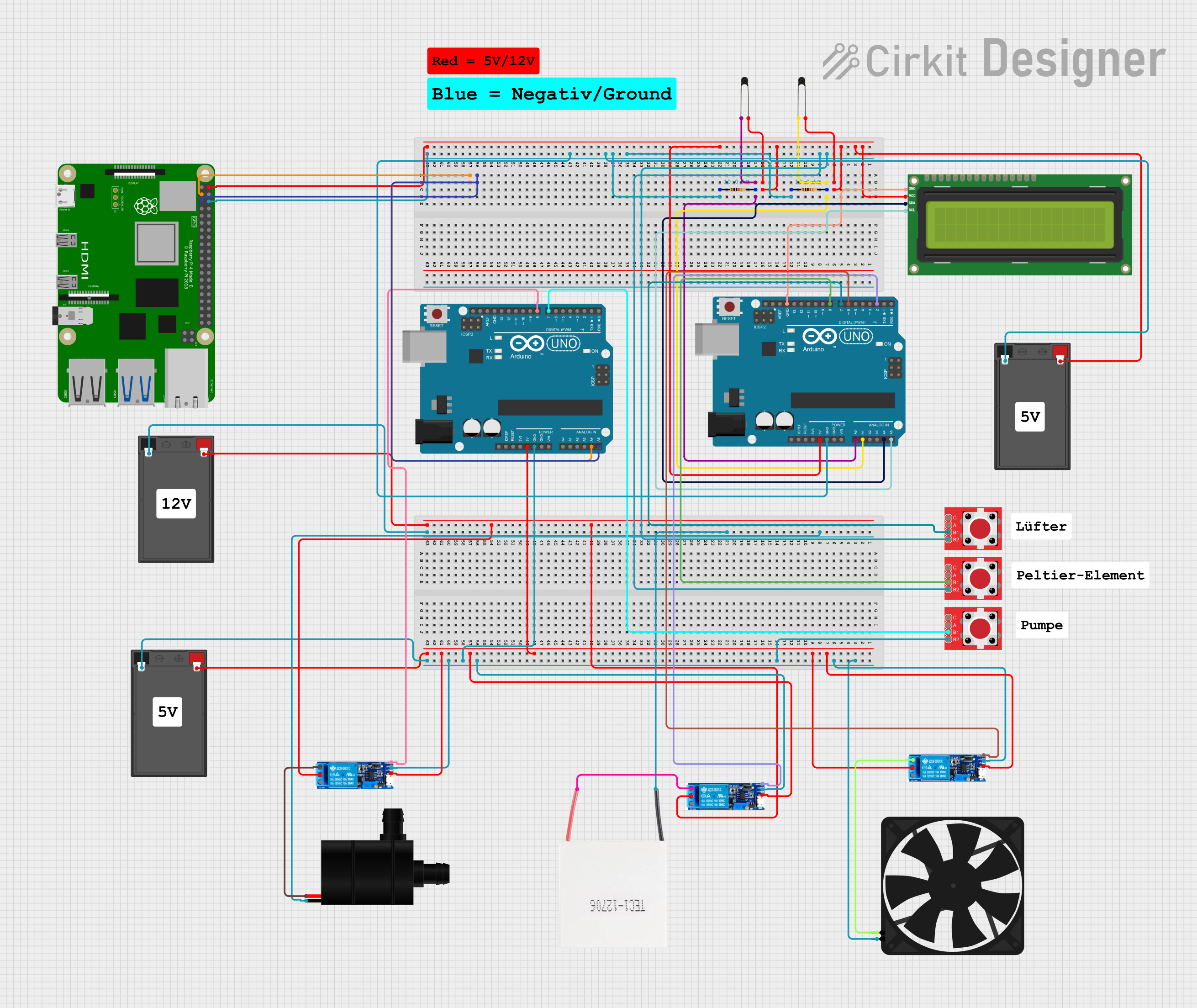
This document provides a detailed overview of a circuit that includes various components such as resistors, thermistors (NTC), an I2C LCD screen, an Arduino UNO, a Raspberry Pi 4B, a battery, LED tactile button breakouts, relay modules, a Peltier module, a water pump, and a fan. The circuit is designed to interface with multiple sensors and actuators, controlled by microcontrollers (Arduino UNO and Raspberry Pi 4B). The document includes a component list, wiring details, and documented code for the microcontrollers.
Component List
Resistor
- Description: A passive electrical component that implements electrical resistance as a circuit element.
- Pins: pin1, pin2
- Properties:
- Resistance: 10,000 Ohms
Arduino UNO
- Description: A microcontroller board based on the ATmega328P.
- Pins: UNUSED, IOREF, Reset, 3.3V, 5V, GND, Vin, A0, A1, A2, A3, A4, A5, SCL, SDA, AREF, D13, D12, D11, D10, D9, D8, D7, D6, D5, D4, D3, D2, D1, D0
NTC (Negative Temperature Coefficient Thermistor)
- Description: A type of resistor whose resistance decreases as the temperature increases.
- Pins: A0, A1
I2C LCD 16x2 Screen
- Description: A 16x2 character LCD display with I2C interface.
- Pins: SCL, SDA, VCC (5V), GND, VDD, VO, RS, RW, E, D0, D1, D2, D3, D4, D5, D6, D7, BLA, BLK
Battery
- Description: A device consisting of one or more electrochemical cells with external connections for powering electrical devices.
- Pins: -, +
LED Tactile Button Breakout
- Description: A breakout board for a tactile button with an integrated LED.
- Pins: C, B1, B2, A
Relay Module 5V-30V
- Description: A relay module that can be controlled with a voltage between 5V and 30V.
- Pins: common contact, normally open, normally closed, trigger, V-, V+
Peltier Module
- Description: A thermoelectric device that can heat or cool depending on the direction of the current.
- Pins: Negative, Positive
Water Pump
- Description: A device used to move liquids.
- Pins: VCC, GND
Fan
- Description: A device used to create airflow.
- Pins: GND, 5V
Raspberry Pi 4B
- Description: A small single-board computer.
- Pins: 3V3, 5V, GPIO2, GPIO3, GND, GPIO4, GPIO14, GPIO15, GPIO17, GPIO18, GPIO27, GPIO22, GPIO23, GPIO24, GPIO10, GPIO9, GPIO25, GPIO11, GPIO8, GPIO7, ID_SD, GPIO5, GPIO6, GPIO12, GPIO13, GPIO19, GPIO16, GPIO26, GPIO20, GPIO21, ID_SC, TR01_TAP, TR00_TAP, TR03_TAP, TR02_TAP, RUN, GLOBAL_EN, ETH, HDMI 0, HDMI 1, CAMERA, AV
Wiring Details
Resistor
Resistor 1:
- pin1: Connected to pin1 of another resistor, B2 of two LED tactile button breakouts, GND of Arduino UNO, GND of Raspberry Pi 4B, and - of a battery.
- pin2: Connected to A1 of Arduino UNO and A0 of an NTC.
Resistor 2:
- pin1: Connected to pin1 of another resistor, B2 of two LED tactile button breakouts, GND of Arduino UNO, GND of Raspberry Pi 4B, and - of a battery.
- pin2: Connected to A0 of Arduino UNO and A0 of an NTC.
Arduino UNO
Arduino UNO 1:
- 5V: Connected to VCC (5V) of I2C LCD screen, + of a battery, and 5V of Raspberry Pi 4B.
- GND: Connected to pin1 of two resistors, B2 of two LED tactile button breakouts, and GND of Raspberry Pi 4B.
- A1: Connected to pin2 of a resistor and A0 of an NTC.
- A0: Connected to pin2 of a resistor and A0 of an NTC.
- A4: Connected to GPIO2 of Raspberry Pi 4B.
- A5: Connected to GPIO3 of Raspberry Pi 4B.
- D8: Connected to B1 of an LED tactile button breakout.
- D7: Connected to B1 of an LED tactile button breakout.
- D6: Connected to trigger of a relay module.
- D2: Connected to trigger of a relay module.
Arduino UNO 2:
- 5V: Connected to V+ and common contact of a relay module.
- GND: Connected to V- of three relay modules, B2 of an LED tactile button breakout, and - of a battery.
- A4: Connected to GPIO2 of Raspberry Pi 4B.
- A5: Connected to GPIO3 of Raspberry Pi 4B.
- D8: Connected to trigger of a relay module.
- D7: Connected to B1 of an LED tactile button breakout.
NTC
NTC 1:
- A0: Connected to pin2 of a resistor and A1 of Arduino UNO.
- A1: Connected to A1 of another NTC, VCC (5V) of I2C LCD screen, + of a battery, and 5V of Raspberry Pi 4B.
NTC 2:
- A0: Connected to pin2 of a resistor and A0 of Arduino UNO.
- A1: Connected to A1 of another NTC, VCC (5V) of I2C LCD screen, + of a battery, and 5V of Raspberry Pi 4B.
I2C LCD 16x2 Screen
- VCC (5V): Connected to A1 of two NTCs, + of a battery, and 5V of Arduino UNO and Raspberry Pi 4B.
- GND: Connected to GND of Arduino UNO.
- SDA: Connected to A4 of Arduino UNO.
- SCL: Connected to A5 of Arduino UNO.
Battery
- +: Connected to VCC (5V) of I2C LCD screen, A1 of two NTCs, and 5V of Arduino UNO and Raspberry Pi 4B.
- -: Connected to pin1 of two resistors, B2 of two LED tactile button breakouts, GND of Arduino UNO, and GND of Raspberry Pi 4B.
LED Tactile Button Breakout
LED Tactile Button Breakout 1:
- B2: Connected to pin1 of two resistors, GND of Arduino UNO, and GND of Raspberry Pi 4B.
- B1: Connected to D8 of Arduino UNO.
LED Tactile Button Breakout 2:
- B2: Connected to pin1 of two resistors, GND of Arduino UNO, and GND of Raspberry Pi 4B.
- B1: Connected to D7 of Arduino UNO.
LED Tactile Button Breakout 3:
- B2: Connected to V- of three relay modules, GND of Arduino UNO, and - of a battery.
- B1: Connected to D7 of Arduino UNO.
Relay Module 5V-30V
Relay Module 1:
- V-: Connected to GND of Arduino UNO and - of a battery.
- V+: Connected to 5V of Arduino UNO.
- trigger: Connected to D6 of Arduino UNO.
- common contact: Connected to V+ of the same relay module and + of a battery.
- normally open: Connected to 5V of a fan.
Relay Module 2:
- V-: Connected to GND of Arduino UNO and - of a battery.
- V+: Connected to 5V of Arduino UNO.
- trigger: Connected to D2 of Arduino UNO.
- common contact: Connected to V+ of the same relay module and + of a battery.
- normally open: Connected to VCC of a water pump.
Relay Module 3:
- V-: Connected to GND of Arduino UNO and - of a battery.
- V+: Connected to 5V of Arduino UNO.
- trigger: Connected to D8 of Arduino UNO.
- common contact: Connected to V+ of the same relay module and + of a battery.
- normally open: Connected