Cirkit Designer
Your all-in-one circuit design IDE
Home /
Project Documentation
ESP32 and MPU6050-Based Motion Sensing System with Wi-Fi Connectivity
Circuit Documentation
Summary
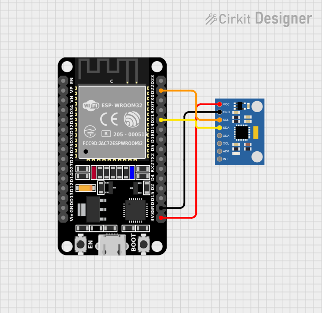
This document provides a detailed overview of a circuit that integrates an ESP32 microcontroller with an MPU6050 Accelerometer + Gyroscope sensor. The ESP32 serves as the main controller, interfacing with the MPU6050 to gather accelerometer and gyroscope data. The connections between the components are described in detail, along with the purpose of each connection.
Component List
ESP32 (30 pin)
- Description: A powerful microcontroller with built-in Wi-Fi and Bluetooth capabilities.
- Pins: EN, VP, VN, D34, D35, D32, D33, D25, D26, D27, D14, D12, D13, GND, Vin, D23, D22, TX0, RX0, D21, D19, D18, D5, TX2, RX2, D4, D2, D15, 3V3
- Purpose in Circuit: Acts as the main controller, interfacing with the MPU6050 sensor to process accelerometer and gyroscope data.
MPU6050 Accelerometer + Gyroscope (Wokwi Compatible)
- Description: A sensor module that provides accelerometer and gyroscope data.
- Pins: INT, AD0, XCL, XDA, SDA, SCL, GND, VCC
- Purpose in Circuit: Provides accelerometer and gyroscope data to the ESP32 for processing.
Wiring Details
ESP32 (30 pin)
- D22 connected to MPU6050 SCL
- D21 connected to MPU6050 SDA
- GND connected to MPU6050 GND
- 3V3 connected to MPU6050 VCC
MPU6050 Accelerometer + Gyroscope (Wokwi Compatible)
- SCL connected to ESP32 D22
- SDA connected to ESP32 D21
- GND connected to ESP32 GND
- VCC connected to ESP32 3V3
Documented Code
There is no code provided for this circuit.
This documentation provides a comprehensive overview of the components and their connections in the circuit. The ESP32 microcontroller interfaces with the MPU6050 sensor to gather and process accelerometer and gyroscope data. The wiring details ensure proper communication between the components.