
Arduino and ESP8266-Based Health Monitoring System with Wi-Fi Connectivity
View and Edit Project In Cirkit Designer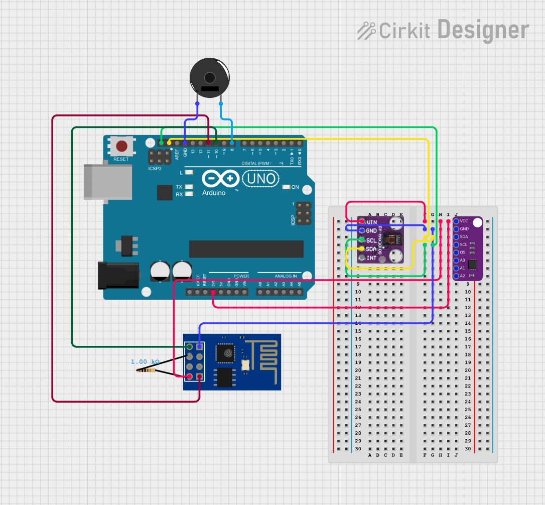
Circuit Documentation
Summary
This document provides a detailed overview of a circuit that integrates an Arduino UNO, an ESP8266 ESP-01 WiFi Module, a MAX30100 pulse oximeter sensor, a MAX30205 temperature sensor, a resistor, and a piezo buzzer. The circuit is designed to measure pulse and temperature, transmit data via WiFi, and provide audible feedback through the buzzer.
Component List
Arduino UNO
- Description: A microcontroller board based on the ATmega328P.
- Pins: UNUSED, IOREF, Reset, 3.3V, 5V, GND, Vin, A0, A1, A2, A3, A4, A5, SCL, SDA, AREF, D13, D12, D11, D10, D9, D8, D7, D6, D5, D4, D3, D2, D1, D0
ESP8266 ESP-01 WiFi Module
- Description: A self-contained WiFi networking solution.
- Pins: TXD, CH_PD, RST, VCC, GND, GPIO_2, GPIO_0, RXD
MAX30100
- Description: Pulse oximeter and heart-rate sensor.
- Pins: Vin, gnd, scl, sda, int
MAX30205
- Description: Temperature sensor.
- Pins: VCC, GND, SDA, SCL, OS, A0, A1, A2
Resistor
- Description: A passive electrical component that implements electrical resistance.
- Pins: pin1, pin2
- Properties:
- Resistance: 1000 Ohms
Piezo Buzzer
- Description: An audio signaling device.
- Pins: pin 1, pin 2
Wiring Details
Arduino UNO
- 3.3V: Connected to VCC of MAX30205, Vin of MAX30100, and VCC of ESP8266 ESP-01 WiFi Module.
- GND: Connected to GND of Piezo Buzzer.
- SDA: Connected to SDA of MAX30205 and sda of MAX30100.
- SCL: Connected to SCL of MAX30205 and scl of MAX30100.
- D11: Connected to RXD of ESP8266 ESP-01 WiFi Module.
- D10: Connected to TXD of ESP8266 ESP-01 WiFi Module.
- D8: Connected to pin 2 of Piezo Buzzer.
ESP8266 ESP-01 WiFi Module
- VCC: Connected to 3.3V of Arduino UNO.
- GND: Connected to GND of MAX30205 and gnd of MAX30100.
- RXD: Connected to D11 of Arduino UNO.
- TXD: Connected to D10 of Arduino UNO.
MAX30100
- Vin: Connected to 3.3V of Arduino UNO.
- gnd: Connected to GND of MAX30205 and GND of ESP8266 ESP-01 WiFi Module.
- scl: Connected to SCL of Arduino UNO and SCL of MAX30205.
- sda: Connected to SDA of Arduino UNO and SDA of MAX30205.
MAX30205
- VCC: Connected to 3.3V of Arduino UNO.
- GND: Connected to gnd of MAX30100 and GND of ESP8266 ESP-01 WiFi Module.
- SDA: Connected to SDA of Arduino UNO and sda of MAX30100.
- SCL: Connected to SCL of Arduino UNO and scl of MAX30100.
Piezo Buzzer
- pin 1: Connected to GND of Arduino UNO.
- pin 2: Connected to D8 of Arduino UNO.
Documented Code
Arduino UNO Code (sketch.ino)
void setup() {
  // put your setup code here, to run once:

}

void loop() {
  // put your main code here, to run repeatedly:

}
This code is a basic template for the Arduino UNO. The setup function is where you initialize your components and the loop function is where you place the main logic that runs repeatedly.