Cirkit Designer
Your all-in-one circuit design IDE
Home /
Project Documentation
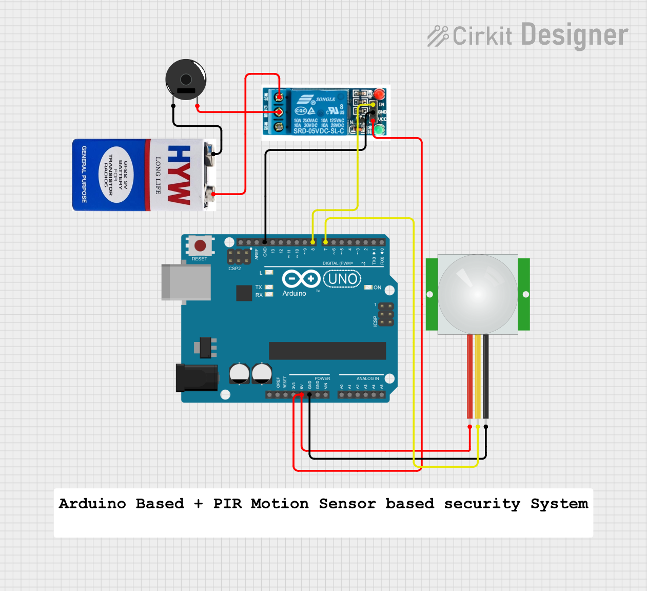
Arduino UNO Motion Detector with PIR Sensor and Piezo Buzzer
Circuit Documentation
Summary
This circuit is a motion detection system using an Arduino UNO, a PIR sensor, a 5V relay, a piezo buzzer, and a 9V battery. The PIR sensor detects motion and sends a signal to the Arduino, which then activates the relay to power the piezo buzzer, producing an audible alert.
Component List
Arduino UNO
- Description: A microcontroller board based on the ATmega328P.
- Pins: UNUSED, IOREF, Reset, 3.3V, 5V, GND, Vin, A0, A1, A2, A3, A4, A5, SCL, SDA, AREF, D13, D12, D11, D10, D9, D8, D7, D6, D5, D4, D3, D2, D1, D0
PIR Sensor
- Description: A passive infrared sensor used to detect motion.
- Pins: VDD, SIG, GND
5V Relay
- Description: An electromechanical switch used to control high voltage devices.
- Pins: Normally Open, Common terminal, Normally Closed, In, GND, VCC
Piezo Buzzer
- Description: An electronic device that produces a tone, alarm, or sound.
- Pins: pin 1, pin 2
9V Battery
- Description: A power source providing 9 volts.
- Pins: +, -
Wiring Details
Arduino UNO
- 5V connected to VDD of PIR Sensor and VCC of 5V Relay
- GND connected to GND of PIR Sensor and GND of 5V Relay
- D8 connected to In of 5V Relay
- D7 connected to SIG of PIR Sensor
PIR Sensor
- VDD connected to 5V of Arduino UNO and VCC of 5V Relay
- GND connected to GND of Arduino UNO
- SIG connected to D7 of Arduino UNO
5V Relay
- VCC connected to 5V of Arduino UNO and VDD of PIR Sensor
- GND connected to GND of Arduino UNO and GND of PIR Sensor
- In connected to D8 of Arduino UNO
- Normally Open connected to - of 9V Battery
- Common terminal connected to pin 2 of Piezo Buzzer
Piezo Buzzer
- pin 1 connected to + of 9V Battery
- pin 2 connected to Common terminal of 5V Relay
9V Battery
- + connected to pin 1 of Piezo Buzzer
- - connected to Normally Open of 5V Relay
Code Documentation
/*
 * Motion Detector
 * This Arduino sketch uses a PIR sensor to detect motion. When motion is
 * detected, it activates a relay which in turn powers a piezo buzzer.
 */

// Pin definitions
const int pirPin = 7; // PIR sensor signal pin
const int relayPin = 8; // Relay control pin

void setup() {
  // Initialize serial communication
  Serial.begin(9600);
  // Initialize PIR sensor pin as input
  pinMode(pirPin, INPUT);
  // Initialize relay pin as output
  pinMode(relayPin, OUTPUT);
  // Ensure relay is off initially
  digitalWrite(relayPin, LOW);
}

void loop() {
  // Read PIR sensor value
  int pirValue = digitalRead(pirPin);
  // If motion is detected
  if (pirValue == HIGH) {
    // Turn on relay
    digitalWrite(relayPin, HIGH);
    // Print motion detected message
    Serial.println("Motion detected!");
  } else {
    // Turn off relay
    digitalWrite(relayPin, LOW);
  }
  // Small delay to avoid bouncing
  delay(100);
}
This code initializes the PIR sensor and relay pins, continuously checks for motion, and activates the relay to power the piezo buzzer when motion is detected.