
ESP32 CAM Controlled Security System with I2C LCD and Solenoid Lock
View and Edit Project In Cirkit Designer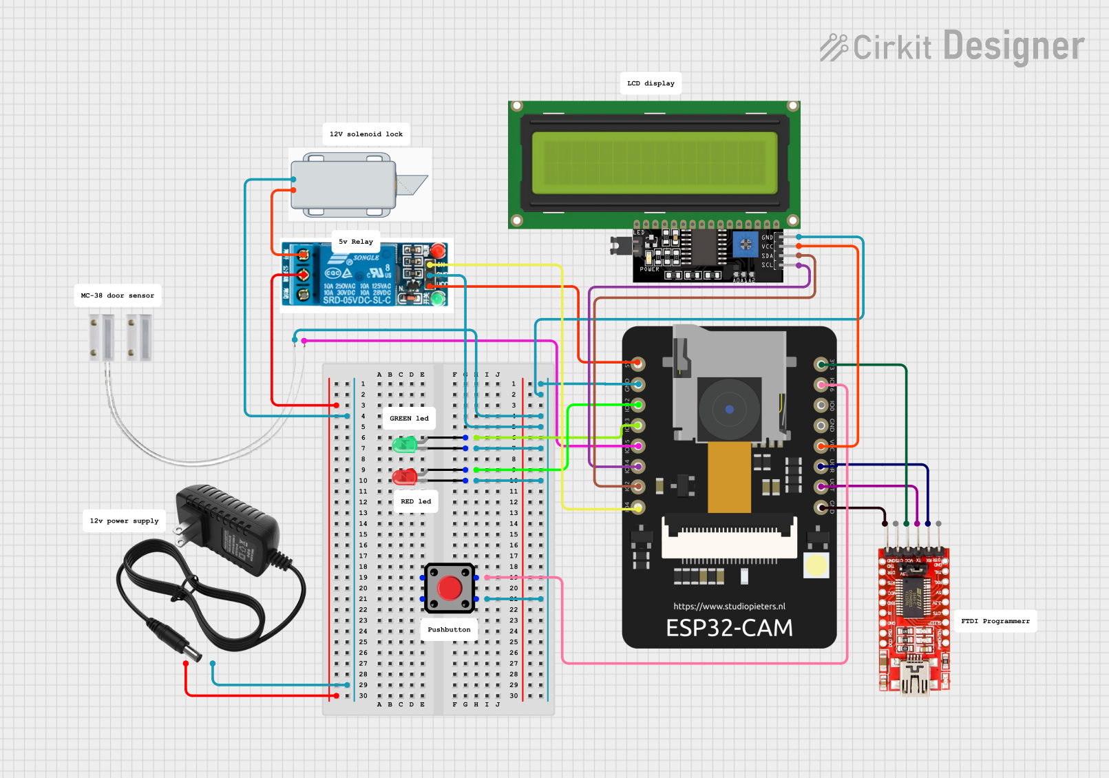
Circuit Documentation
Summary
This circuit is designed to interface an ESP32 CAM with various peripherals including an FTDI Programmer for serial communication, an LCD Display for user interface, LEDs for status indication, a relay to control a 12V Solenoid Lock, a magnetic door sensor (Door MC-38), and a pushbutton for user input. The ESP32 CAM serves as the central processing unit, handling sensor inputs, controlling the relay, and communicating with the LCD Display via I2C protocol. The FTDI Programmer is used for programming the ESP32 CAM. The circuit is powered by a 12V power supply, which also powers the 12V Solenoid Lock through the relay.
Component List
FTDI Programmer
- Description: A USB to serial interface adapter used for programming microcontrollers.
- Pins: DTR, RX, TX, VCC, CTS, GND
LCD Display 16x4 I2C
- Description: A 16x4 character LCD display with an I2C interface for displaying information.
- Pins: SCL, SDA, VCC, GND
ESP32 CAM
- Description: A microcontroller with integrated Wi-Fi and camera support, suitable for IoT applications.
- Pins: 5V, GND, GPIO12, GPIO13, GPIO15, GPIO14, GPIO2, GPIO4, 3.3V, GPIO16, GPIO0, 3.3V / 5V / P_OUT, GPIO3 / RX, GPIO1 / TX
LED: Two Pin (red)
- Description: A red LED for status indication.
- Pins: cathode, anode
LED: Two Pin (green)
- Description: A green LED for status indication.
- Pins: cathode, anode
5V Relay
- Description: An electromechanical switch used to control high power devices.
- Pins: Normally Open, Common terminal, Normally Closed, In, GND, VCC
12V Solenoid Lock
- Description: An electrically actuated lock that operates on 12V.
- Pins: -, +
Door MC-38
- Description: A magnetic door sensor used to detect the opening and closing of doors.
- Pins: S, GND
12V Power Supply
- Description: A power supply unit that provides 12V DC output.
- Pins: +, -
Pushbutton
- Description: A momentary pushbutton switch for user input.
- Pins: Pin 2, Pin 1, Pin 3, Pin 4
Wiring Details
FTDI Programmer
- DTR: Not connected
- RX: Connected to ESP32 CAM TX (GPIO1 / TX)
- TX: Connected to ESP32 CAM RX (GPIO3 / RX)
- VCC: Connected to ESP32 CAM 3.3V
- CTS: Not connected
- GND: Connected to ESP32 CAM GND
LCD Display 16x4 I2C
- SCL: Connected to ESP32 CAM GPIO14
- SDA: Connected to ESP32 CAM GPIO2
- VCC: Connected to ESP32 CAM 3.3V / 5V / P_OUT
- GND: Connected to ESP32 CAM GND
ESP32 CAM
- 5V: Connected to 5V Relay VCC
- GND: Common ground with multiple components
- GPIO12: Connected to Red LED anode
- GPIO13: Connected to Green LED anode
- GPIO15: Connected to Door MC-38 S
- GPIO14: Connected to LCD Display SCL
- GPIO2: Connected to LCD Display SDA
- GPIO4: Connected to 5V Relay In
- 3.3V: Connected to FTDI Programmer VCC
- GPIO16: Connected to Pushbutton Pin 3
- GPIO0: Not connected
- 3.3V / 5V / P_OUT: Connected to LCD Display VCC
- GPIO3 / RX: Connected to FTDI Programmer TX
- GPIO1 / TX: Connected to FTDI Programmer RX
LED: Two Pin (red)
- cathode: Connected to common ground
- anode: Connected to ESP32 CAM GPIO12
LED: Two Pin (green)
- cathode: Connected to common ground
- anode: Connected to ESP32 CAM GPIO13
5V Relay
- Normally Open: Connected to 12V Solenoid Lock +
- Common terminal: Connected to 12V Power Supply +
- Normally Closed: Not connected
- In: Connected to ESP32 CAM GPIO4
- GND: Connected to common ground
- VCC: Connected to ESP32 CAM 5V
12V Solenoid Lock
- -: Connected to 12V Power Supply -
- +: Connected to 5V Relay Normally Open
Door MC-38
- S: Connected to ESP32 CAM GPIO15
- GND: Connected to common ground
12V Power Supply
- +: Connected to 5V Relay Common terminal
- -: Connected to 12V Solenoid Lock -
Pushbutton
- Pin 2: Connected to common ground
- Pin 1: Not connected
- Pin 3: Connected to ESP32 CAM GPIO16
- Pin 4: Not connected
Documented Code
FTDI Programmer Code (sketch.ino)
// The provided code snippet is incomplete and does not contain functional code.
// Please replace this with the actual code for the FTDI Programmer.
Additional Documentation (documentation.txt)
// There is no additional code documentation provided.
// Please include any relevant code documentation here.
Please note that the provided code snippets are placeholders and should be replaced with the actual code used in the microcontroller programming. The actual functionality and implementation details would be documented here once the full code is available.