
Arduino Nano-Based Wireless Sensor Module with MPU6050 and NRF24L01
View and Edit Project In Cirkit Designer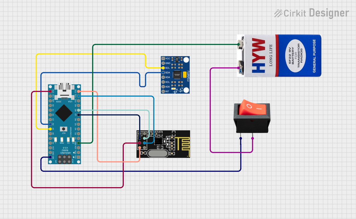
Circuit Documentation
Summary
This document provides a detailed overview of a circuit that includes an Arduino Nano, an NRF24L01 wireless module, an InvenSense MPU6050 sensor, a 9V battery, and a rocker switch. The circuit is designed to interface the Arduino Nano with the NRF24L01 for wireless communication and the MPU6050 for motion sensing. The power is supplied by a 9V battery controlled by a rocker switch.
Component List
Arduino Nano
- Description: A small, complete, and breadboard-friendly board based on the ATmega328P.
- Pins: D1/TX, D0/RX, RESET, GND, D2, D3, D4, D5, D6, D7, D8, D9, D10, D11/MOSI, D12/MISO, VIN, 5V, A7, A6, A5, A4, A3, A2, A1, A0, AREF, 3V3, D13/SCK
NRF24L01
- Description: A wireless transceiver module for low-power, high-speed communication.
- Pins: IRQ (not used), MOSI, CSN, VCC (3V), GND, CE, SCK, MISO
InvenSense MPU6050
- Description: A 6-axis motion tracking device that combines a 3-axis gyroscope and a 3-axis accelerometer.
- Pins: VCC, GND, SCL, SDA, XDA, XCL, AD0, INT
9V Battery
- Description: A standard 9V battery used to power the circuit.
- Pins: +, -
Rocker Switch
- Description: A simple on/off switch to control the power supply from the 9V battery.
- Pins: output, input
Wiring Details
Arduino Nano
- GND: Connected to the GND pin of the 9V battery.
- D7: Connected to the CE pin of the NRF24L01.
- D8: Connected to the CSN pin of the NRF24L01.
- D11/MOSI: Connected to the MOSI pin of the NRF24L01.
- D12/MISO: Connected to the MISO pin of the NRF24L01.
- VIN: Connected to the input pin of the rocker switch.
- A5: Connected to the SCL pin of the InvenSense MPU6050.
- A4: Connected to the SDA pin of the InvenSense MPU6050.
- D13/SCK: Connected to the SCK pin of the NRF24L01.
NRF24L01
- CE: Connected to the D7 pin of the Arduino Nano.
- CSN: Connected to the D8 pin of the Arduino Nano.
- MOSI: Connected to the D11/MOSI pin of the Arduino Nano.
- MISO: Connected to the D12/MISO pin of the Arduino Nano.
- SCK: Connected to the D13/SCK pin of the Arduino Nano.
InvenSense MPU6050
- SCL: Connected to the A5 pin of the Arduino Nano.
- SDA: Connected to the A4 pin of the Arduino Nano.
9V Battery
- -: Connected to the GND pin of the Arduino Nano.
- +: Connected to the output pin of the rocker switch.
Rocker Switch
- input: Connected to the VIN pin of the Arduino Nano.
- output: Connected to the + pin of the 9V battery.
Documented Code
Arduino Nano Code
void setup() {
  // put your setup code here, to run once:

}

void loop() {
  // put your main code here, to run repeatedly:

}
This code is a basic template for the Arduino Nano. The setup() function is where you initialize your components and settings, and the loop() function is where the main logic of your program runs repeatedly.
Additional Documentation
This section is reserved for any additional documentation or notes related to the code or circuit.