
Arduino and ESP8266-Based Smart Servo Control System with IR Sensors
View and Edit Project In Cirkit Designer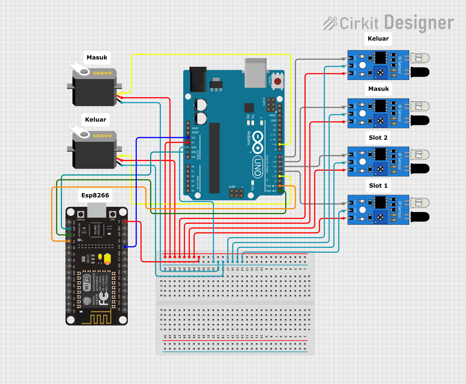
Circuit Documentation
Summary
This circuit involves an Arduino UNO microcontroller, an ESP8266 NodeMCU, multiple IR sensors, and servos. The Arduino UNO serves as the main controller, interfacing with the IR sensors and servos. The ESP8266 NodeMCU is used for wireless communication. The IR sensors detect obstacles, and the servos perform actions based on the sensor inputs.
Component List
Arduino UNO
- Description: A microcontroller board based on the ATmega328P.
- Pins: UNUSED, IOREF, Reset, 3.3V, 5V, GND, Vin, A0, A1, A2, A3, A4, A5, SCL, SDA, AREF, D13, D12, D11, D10, D9, D8, D7, D6, D5, D4, D3, D2, D1, D0
Servo (x2)
- Description: A servo motor used for precise control of angular position.
- Pins: gnd, vcc, pulse
IR Sensor (x5)
- Description: An infrared sensor used for obstacle detection.
- Pins: out, gnd, vcc
ESP8266 NodeMCU
- Description: A low-cost Wi-Fi microchip with full TCP/IP stack and microcontroller capability.
- Pins: D0, D1, D2, D3, D4, 3V3, GND, D5, D6, D7, D8, RX, TX, A0, RSV, SD3, SD2, SD1, CMD, SD0, CLK, EN, RST, VIN
Comment (x8)
- Description: Placeholder for comments in the circuit design.
- Pins: None
Wiring Details
Arduino UNO
- GND: Connected to GND of all IR sensors and servos.
- 5V: Connected to vcc of all IR sensors and servos.
- 3.3V: Connected to 3V3 of ESP8266 NodeMCU.
- D9: Connected to pulse of Servo 1.
- D7: Connected to out of IR Sensor 1.
- D6: Connected to out of IR Sensor 2.
- D5: Connected to out of IR Sensor 3.
- D4: Connected to out of IR Sensor 4.
- D3: Connected to pulse of Servo 2.
- D1: Connected to RX of ESP8266 NodeMCU.
- D0: Connected to TX of ESP8266 NodeMCU.
Servo 1
- gnd: Connected to GND of Arduino UNO.
- vcc: Connected to 5V of Arduino UNO.
- pulse: Connected to D9 of Arduino UNO.
Servo 2
- gnd: Connected to GND of Arduino UNO.
- vcc: Connected to 5V of Arduino UNO.
- pulse: Connected to D3 of Arduino UNO.
IR Sensor 1
- gnd: Connected to GND of Arduino UNO.
- vcc: Connected to 5V of Arduino UNO.
- out: Connected to D7 of Arduino UNO.
IR Sensor 2
- gnd: Connected to GND of Arduino UNO.
- vcc: Connected to 5V of Arduino UNO.
- out: Connected to D6 of Arduino UNO.
IR Sensor 3
- gnd: Connected to GND of Arduino UNO.
- vcc: Connected to 5V of Arduino UNO.
- out: Connected to D5 of Arduino UNO.
IR Sensor 4
- gnd: Connected to GND of Arduino UNO.
- vcc: Connected to 5V of Arduino UNO.
- out: Connected to D4 of Arduino UNO.
IR Sensor 5
- gnd: Connected to GND of Arduino UNO.
- vcc: Connected to 5V of Arduino UNO.
- out: Not connected.
ESP8266 NodeMCU
- VIN: Connected to 5V of Arduino UNO.
- 3V3: Connected to 3.3V of Arduino UNO.
- GND: Connected to GND of Arduino UNO.
- RX: Connected to D1 of Arduino UNO.
- TX: Connected to D0 of Arduino UNO.
Documented Code
Arduino UNO Code (sketch.ino)
void setup() {
  // put your setup code here, to run once:

}

void loop() {
  // put your main code here, to run repeatedly:

}
Documentation (documentation.txt)
This documentation provides a comprehensive overview of the circuit, including a summary, component list, wiring details, and the code used in the microcontroller.