Cirkit Designer
Your all-in-one circuit design IDE
Home /
Project Documentation
Arduino UNO Controlled Red LED Blinker
Circuit Documentation
Summary of the Circuit
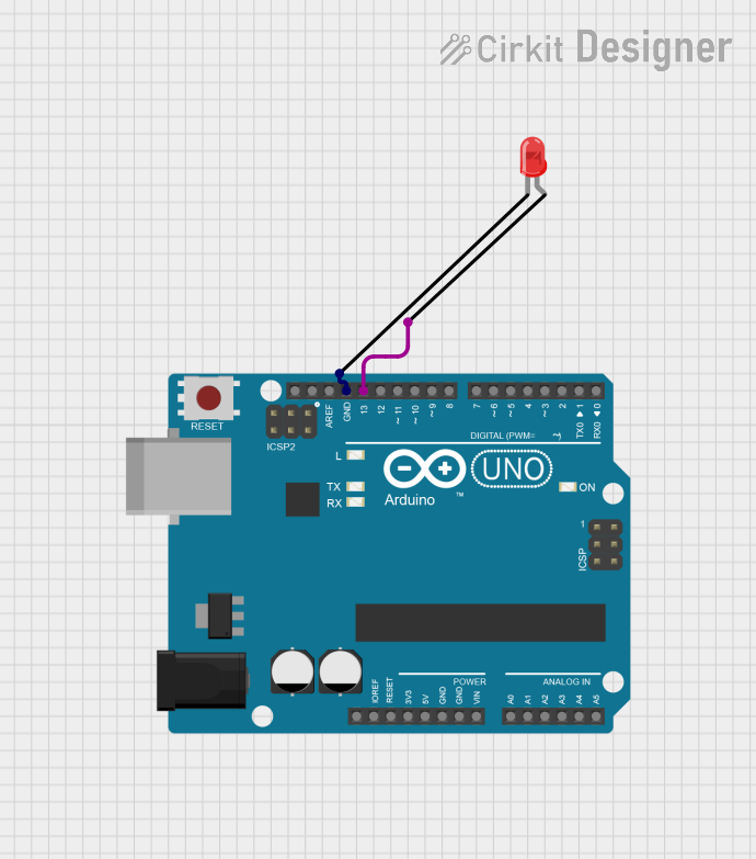
This circuit consists of an Arduino UNO microcontroller board and a two-pin red LED. The Arduino UNO is used to control the LED, turning it on or off. The LED is connected to one of the digital pins of the Arduino (D13) and to the ground (GND). This simple setup can be used to demonstrate basic digital output functionality of the Arduino UNO.
Component List
Arduino UNO
- Description: A microcontroller board based on the ATmega328P. It has 14 digital input/output pins, 6 analog inputs, a 16 MHz quartz crystal, a USB connection, a power jack, an ICSP header, and a reset button.
- Purpose: Acts as the main controller for the circuit, capable of executing programmed instructions and interfacing with various electronic components.
LED: Two Pin (red)
- Description: A basic red light-emitting diode with two pins: an anode and a cathode.
- Purpose: Serves as an indicator light, which can be turned on or off by the Arduino UNO.
Wiring Details
Arduino UNO
- Digital Pin 13 (D13): Connected to the anode of the red LED.
- Ground (GND): Connected to the cathode of the red LED.
LED: Two Pin (red)
- Anode: Connected to Digital Pin 13 (D13) on the Arduino UNO.
- Cathode: Connected to Ground (GND) on the Arduino UNO.
Documented Code
void setup() {
  // Initialize digital pin 13 as an output.
  pinMode(13, OUTPUT);
}

void loop() {
  // Turn the LED on (HIGH is the voltage level)
  digitalWrite(13, HIGH);
  // Wait for a second
  delay(1000);
  // Turn the LED off by making the voltage LOW
  digitalWrite(13, LOW);
   // Wait for a second
  delay(1000);
}
File Name: sketch.ino
Description: This code is written for the Arduino UNO microcontroller. It initializes digital pin 13 as an output in the setup() function. In the loop() function, it turns the LED on and off with a one-second interval between each state change.