Cirkit Designer
Your all-in-one circuit design IDE
Home /
Project Documentation
Arduino Mega 2560-Based Multi-Sensor Monitoring System with GSM Alerts
Circuit Documentation
Summary
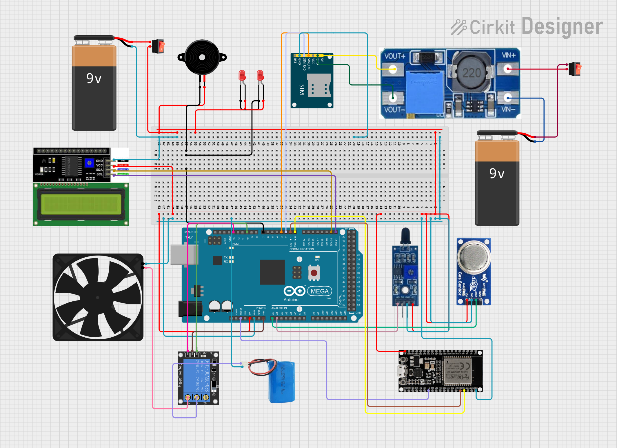
This document provides a detailed overview of a circuit designed to interface various components with an Arduino Mega 2560 microcontroller. The circuit includes sensors, communication modules, output devices, and power management components. The primary function of the circuit is to monitor environmental parameters using sensors, display information, communicate over GSM, and control peripheral devices like LEDs, a piezo speaker, and a fan.
Component List
9V Battery
- Description: Provides power to the circuit.
Arduino Mega 2560
- Description: The main microcontroller board based on the ATmega2560, used for controlling the logic of the circuit.
Step Up Boost Power Converter, Adjustable Voltage Regulator
- Description: Increases the voltage level from the input source to a desired level at the output.
Flame Sensor
- Description: Detects the presence of a flame or fire.
SIM800L GSM Module
- Description: Provides GSM communication capabilities to the circuit.
MQ6 Gas Sensor
- Description: Detects the presence of LPG, butane, propane, methane, alcohol, hydrogen, and smoke.
LCD I2C Display
- Description: Displays information to the user via a liquid crystal display with an I2C interface.
LED: Two Pin (red)
- Description: A red light-emitting diode used as an indicator.
Piezo Speaker
- Description: An electronic device that emits sound when an electric current is passed through it.
5V Battery
- Description: Provides a 5V power supply to the circuit.
Rocker Switch
- Description: A switch that allows current to flow when in the 'on' position and breaks the circuit when 'off'.
Fan
- Description: An electric fan used for cooling purposes.
1-Channel Relay (5V 10A)
- Description: An electromechanical switch used to control a high power circuit with a low power signal.
ESP32 38 PINS
- Description: A microcontroller with Wi-Fi and Bluetooth capabilities for IoT applications.
Wiring Details
9V Battery
- Provides power to the Step Up Boost Power Converter through a rocker switch.
Arduino Mega 2560
- Connected to various components for control and data acquisition:
- Digital pins control LEDs and relay module.
- Analog pins read data from sensors.
- I2C pins interface with the LCD display.
- Serial communication with ESP32.
Step Up Boost Power Converter, Adjustable Voltage Regulator
- Steps up the voltage from the 9V battery to power the SIM800L GSM Module.
Flame Sensor
- Powered by the Arduino Mega 2560 and sends analog data back to it.
SIM800L GSM Module
- Receives power from the Step Up Boost Power Converter.
- Communicates with the Arduino Mega 2560 via serial connection.
MQ6 Gas Sensor
- Powered by the Arduino Mega 2560 and sends analog data back to it.
LCD I2C Display
- Powered by the Arduino Mega 2560 and communicates over the I2C bus.
LED: Two Pin (red)
- Controlled by the Arduino Mega 2560 for indication purposes.
Piezo Speaker
- Driven by the Arduino Mega 2560 to emit sound.
5V Battery
- Provides power to the relay module.
Rocker Switch
- Controls the power flow from the batteries to the circuit.
Fan
- Powered by the relay module and controlled by the Arduino Mega 2560.
1-Channel Relay (5V 10A)
- Controlled by the Arduino Mega 2560 to switch the fan on and off.
ESP32 38 PINS
- Communicates with the Arduino Mega 2560 and provides additional processing power and connectivity options.
Documented Code
Arduino Mega 2560 Code (sketch.ino)
void setup() {
  // put your setup code here, to run once:

}

void loop() {
  // put your main code here, to run repeatedly:

}
Note: The provided code is a template and does not contain any functional implementation. It is expected that the user will add the necessary setup and loop code to control the circuit components as per the requirements.