
Arduino UNO Controlled Dual 12V PWM Fan System with Speed Adjustment
View and Edit Project In Cirkit Designer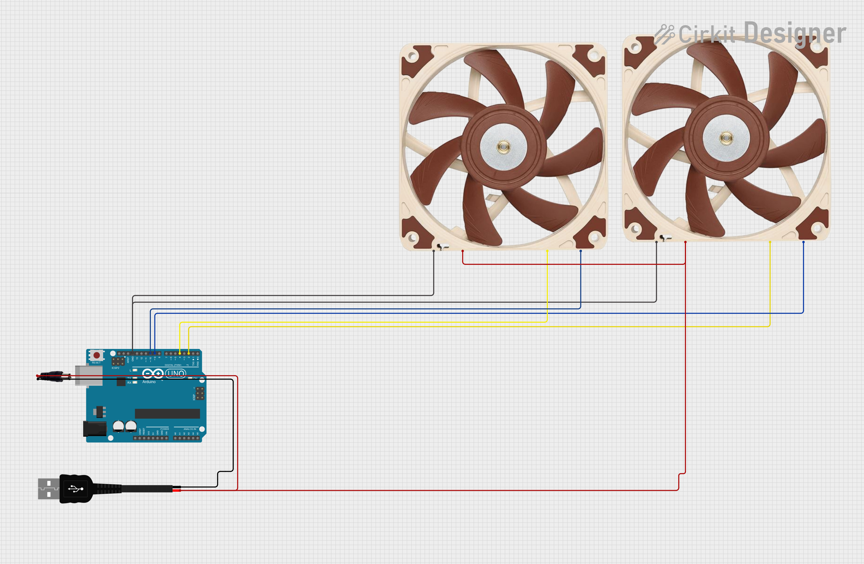
Circuit Documentation
Summary
This circuit is designed to control two 12V PWM fans using an Arduino UNO. The Arduino reads the tachometer signals from the fans and adjusts their speed using PWM signals. The speed of the fans is increased from 0% to 100% in 10% increments, with a 10-second delay between each increment. The circuit is powered through a USB connection and a power jack.
Component List
Arduino UNO
- Description: A microcontroller board based on the ATmega328P.
- Pins: UNUSED, IOREF, Reset, 3.3V, 5V, GND, Vin, A0, A1, A2, A3, A4, A5, SCL, SDA, AREF, D13, D12, D11, D10, D9, D8, D7, D6, D5, D4, D3, D2, D1, D0
12V PWM Fan (120mm)
- Description: A 120mm fan with PWM control and tachometer output.
- Pins: GND, +12V, TACH, PWM
12V PWM Fan (120mm)
- Description: A 120mm fan with PWM control and tachometer output.
- Pins: GND, +12V, TACH, PWM
USB male 2 pin connection
- Description: A USB male connector for power supply.
- Pins: Negative -, Positive +
Power Jack
- Description: A power jack for connecting an external power source.
- Pins: POSITIF, NEGATIF
Wiring Details
Arduino UNO
GND is connected to:
- GND of 12V PWM Fan (120mm)
- GND of another 12V PWM Fan (120mm)
D10 is connected to:
- PWM of 12V PWM Fan (120mm)
D9 is connected to:
- PWM of another 12V PWM Fan (120mm)
D4 is connected to:
- TACH of 12V PWM Fan (120mm)
D2 is connected to:
- TACH of another 12V PWM Fan (120mm)
12V PWM Fan (120mm)
GND is connected to:
- GND of Arduino UNO
- GND of another 12V PWM Fan (120mm)
PWM is connected to:
- D10 of Arduino UNO
TACH is connected to:
- D4 of Arduino UNO
+12V is connected to:
- POSITIF of Power Jack
12V PWM Fan (120mm)
GND is connected to:
- GND of Arduino UNO
- GND of another 12V PWM Fan (120mm)
PWM is connected to:
- D9 of Arduino UNO
TACH is connected to:
- D2 of Arduino UNO
+12V is connected to:
- POSITIF of Power Jack
USB male 2 pin connection
Positive + is connected to:
- POSITIF of Power Jack
Negative - is connected to:
- NEGATIF of Power Jack
Power Jack
POSITIF is connected to:
- +12V of 12V PWM Fan (120mm)
- +12V of another 12V PWM Fan (120mm)
- Positive + of USB male 2 pin connection
NEGATIF is connected to:
- Negative - of USB male 2 pin connection
Code Documentation
/*
 * This Arduino sketch controls two 12V PWM fans. It reads the tachometer
 * signals from the fans and adjusts their speed using PWM signals. The
 * speed of the fans is increased from 0% to 100% in 10% increments, with
 * a 10-second delay between each increment.
 */

const int fan1TachPin = 2; // Tachometer pin for Fan 1
const int fan1PwmPin = 9;  // PWM control pin for Fan 1
const int fan2TachPin = 4; // Tachometer pin for Fan 2
const int fan2PwmPin = 10; // PWM control pin for Fan 2

void setup() {
  // Initialize serial communication
  Serial.begin(9600);
  // Set pin modes
  pinMode(fan1TachPin, INPUT);
  pinMode(fan1PwmPin, OUTPUT);
  pinMode(fan2TachPin, INPUT);
  pinMode(fan2PwmPin, OUTPUT);
}

void loop() {
  for (int dutyCycle = 0; dutyCycle <= 255; dutyCycle += 26) {
    // Control fan speeds
    analogWrite(fan1PwmPin, dutyCycle);
    analogWrite(fan2PwmPin, dutyCycle);
    // Print current duty cycle to serial monitor
    Serial.print("Duty Cycle: ");
    Serial.println(dutyCycle);
    // Delay for 10 seconds
    delay(10000);
  }
}
This code initializes the pins for the tachometer and PWM control of the two fans. In the loop function, it gradually increases the duty cycle of the PWM signal from 0% to 100% in 10% increments, with a 10-second delay between each increment. The current duty cycle is printed to the serial monitor.