
Arduino Nano-Based Smart Sensor System with Wi-Fi Connectivity
View and Edit Project In Cirkit Designer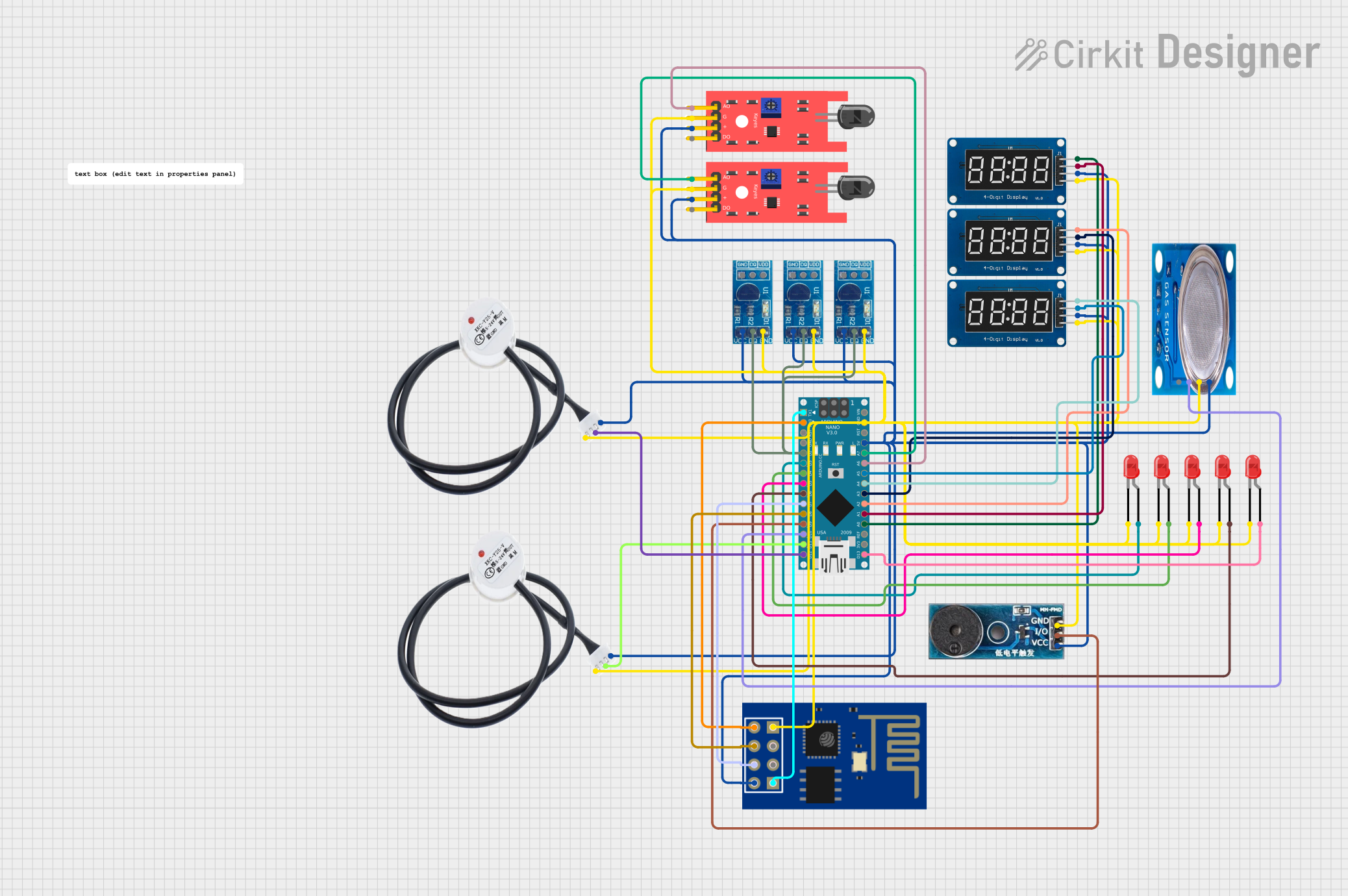
Circuit Documentation
Summary
This circuit involves an Arduino Nano microcontroller interfacing with various sensors and modules, including temperature sensors (DS18B20), flame sensors (KY-026), a gas sensor (MQ-5), a water level sensor, a buzzer module, and multiple LEDs. Additionally, it includes an ESP-01 module for Wi-Fi communication and TM1637 modules for display purposes. The Arduino Nano is programmed to read sensor data, control LEDs, and display information on the TM1637 modules.
Component List
Arduino Nano
- Description: A small, complete, and breadboard-friendly board based on the ATmega328P.
- Pins: D1/TX, D0/RX, RESET, GND, D2, D3, D4, D5, D6, D7, D8, D9, D10, D11/MOSI, D12/MISO, VIN, 5V, A7, A6, A5, A4, A3, A2, A1, A0, AREF, 3V3, D13/SCK
TM1637
- Description: A 4-digit 7-segment display module.
- Pins: CLK, DIO, VCC, GND
DS18B20 Module
- Description: A digital temperature sensor.
- Pins: VCC, DQ, GND
KY-026 Flame Sensor
- Description: A flame sensor module.
- Pins: A0, GND, VCC, D0
LED: Two Pin (red)
- Description: A standard red LED.
- Pins: cathode, anode
MQ-5
- Description: A gas sensor module.
- Pins: VCC, GND, Digi Out, Analog out
Non-contact Water Level Sensor
- Description: A sensor to detect water levels without direct contact.
- Pins: VCC, GND, SIG
Buzzer Module
- Description: A module to produce sound.
- Pins: GND, Vcc, I/O
ESP-01
- Description: A Wi-Fi module based on the ESP8266.
- Pins: GND, GPIO02, GPIO0, RX, VCC, RST, CH_PD, TX
Wiring Details
Arduino Nano
- D1/TX: Connected to ESP-01 RX
- D0/RX: Connected to ESP-01 TX
- D2: Connected to DS18B20 Module DQ
- D3: Connected to LED anode
- D4: Connected to LED anode
- D5: Connected to LED anode
- D6: Connected to LED anode
- D7: Connected to ESP-01 RST
- D8: Connected to ESP-01 CH_PD
- D9: Connected to Buzzer Module I/O
- D10: Connected to MQ-5 Digi Out
- D11/MOSI: Connected to Non-contact Water Level Sensor SIG
- D12/MISO: Connected to Non-contact Water Level Sensor SIG
- D13/SCK: Connected to LED anode
- A7: Connected to KY-026 Flame Sensor A0
- A6: Connected to KY-026 Flame Sensor A0
- A5: Connected to TM1637 DIO
- A4: Connected to TM1637 CLK
- A3: Connected to TM1637 DIO
- A2: Connected to TM1637 CLK
- A1: Connected to TM1637 DIO
- A0: Connected to TM1637 CLK
- 5V: Connected to VCC of all sensors and modules
- GND: Connected to GND of all sensors and modules
TM1637
- CLK: Connected to Arduino Nano A4, A2, A0
- DIO: Connected to Arduino Nano A5, A3, A1
- VCC: Connected to Arduino Nano 5V
- GND: Connected to Arduino Nano GND
DS18B20 Module
- VCC: Connected to Arduino Nano 5V
- DQ: Connected to Arduino Nano D2
- GND: Connected to Arduino Nano GND
KY-026 Flame Sensor
- A0: Connected to Arduino Nano A7, A6
- GND: Connected to Arduino Nano GND
- VCC: Connected to Arduino Nano 5V
LED: Two Pin (red)
- anode: Connected to Arduino Nano D3, D4, D5, D6, D13/SCK
- cathode: Connected to Arduino Nano GND
MQ-5
- VCC: Connected to Arduino Nano 5V
- GND: Connected to Arduino Nano GND
- Digi Out: Connected to Arduino Nano D10
Non-contact Water Level Sensor
- VCC: Connected to Arduino Nano 5V
- GND: Connected to Arduino Nano GND
- SIG: Connected to Arduino Nano D11/MOSI, D12/MISO
Buzzer Module
- GND: Connected to Arduino Nano GND
- Vcc: Connected to Arduino Nano 5V
- I/O: Connected to Arduino Nano D9
ESP-01
- GND: Connected to Arduino Nano GND
- RX: Connected to Arduino Nano D1/TX
- TX: Connected to Arduino Nano D0/RX
- VCC: Connected to Arduino Nano 5V
- RST: Connected to Arduino Nano D7
- CH_PD: Connected to Arduino Nano D8
Code Documentation
Arduino Nano Code
int x = 1234;

#include "TM1637.h"
TM1637 tm1637(2,3);

void setup() {
  tm1637.init();
  tm1637.set(BRIGHT_TYPICAL);
}

void loop() {
    x = x + 1;
    tm1637.point(POINT_ON);
    tm1637.display(x);
    delay(500);
    tm1637.point(POINT_OFF);
    tm1637.display(x);
    delay(500);
}
- Libraries Used: TM1637.h
- Initialization: The TM1637 display is initialized and set to typical brightness in the
setup()function. - Main Loop: In the
loop()function, a counterxis incremented, and its value is displayed on the TM1637 display. The display's decimal point is toggled on and off with a 500ms delay between each state.
This documentation provides a comprehensive overview of the circuit, including a summary, detailed component list, wiring details, and code documentation.