Cirkit Designer
Your all-in-one circuit design IDE
Home /
Project Documentation
Solar-Powered 12V Battery Charging System with Power Inverter

Solar Power System Circuit Documentation
Summary
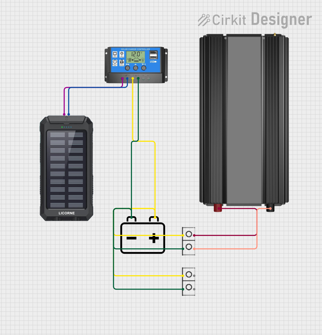
This document provides a detailed overview of a solar power system circuit designed to harness solar energy, store it in a 12v battery, and convert it to AC power using a power inverter. The system includes a solar charger power bank, a solar charge controller, a 12v battery, a power inverter, and wire connectors to establish the necessary connections.
Component List
Solar Charger Power Bank
- Description: A device that collects solar energy and provides charging capabilities.
- Pins:
+(Positive),-(Negative)
Solar Charge Controller
- Description: Regulates the energy flow from the solar charger to the battery and load.
- Pins:
Solar Cell +,Solar Cell -,Battery +,Battery -,Load +,Load -
12v Battery
- Description: Stores electrical energy for later use.
- Pins:
+(Positive),-(Negative)
Power Inverter
- Description: Converts DC power from the battery to AC power.
- Pins:
+(Positive),-(Negative)
Wire Connector
- Description: Used to connect various components within the circuit.
- Pins:
+(Positive),-(Negative)
Wiring Details
Solar Charger Power Bank
- Positive Pin: Connected to the
Solar Cell +pin of the Solar Charge Controller. - Negative Pin: Connected to the
Solar Cell -pin of the Solar Charge Controller.
Solar Charge Controller
- Solar Cell +: Connected to the positive pin of the Solar Charger Power Bank.
- Solar Cell -: Connected to the negative pin of the Solar Charger Power Bank.
- Battery +: Connected to the positive pin of the 12v Battery and the positive pin of a wire connector.
- Battery -: Connected to the negative pin of the 12v Battery and the negative pin of a wire connector.
- Load +: Not connected in this circuit.
- Load -: Not connected in this circuit.
12v Battery
- Positive Pin: Connected to the
Battery +pin of the Solar Charge Controller and the positive pin of a wire connector. - Negative Pin: Connected to the
Battery -pin of the Solar Charge Controller and the negative pin of a wire connector.
Power Inverter
- Positive Pin: Connected to the positive pin of a wire connector.
- Negative Pin: Connected to the negative pin of a wire connector.
Wire Connector
- Positive Pin: Interconnects the
Battery +pin of the Solar Charge Controller, the positive pin of the 12v Battery, and the positive pin of the Power Inverter. - Negative Pin: Interconnects the
Battery -pin of the Solar Charge Controller, the negative pin of the 12v Battery, and the negative pin of the Power Inverter.
Code Documentation
No microcontroller code is provided for this circuit, as the components used do not require any embedded code for operation. The system operates on direct electrical connections and the functionality of the components is hardware-based.