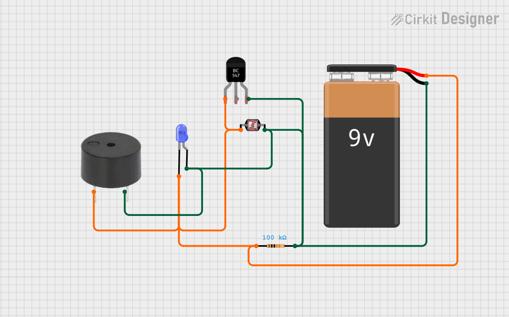
LDR-Controlled LED and Buzzer Circuit with BC547 Transistor

Circuit Documentation
Summary of the Circuit
This circuit appears to be a light-sensitive switch that controls a buzzer and an LED. The circuit uses a 9V battery as a power source. A photocell (LDR) is used to sense the ambient light level. The BC547 transistor acts as a switch, controlling the current flow to the buzzer and LED based on the resistance of the LDR. The resistor provides a fixed resistance for the voltage divider configuration with the LDR. When the light level decreases, the resistance of the LDR increases, causing the transistor to allow current flow, thus activating the buzzer and lighting up the LED.
Component List
9V Battery
- Description: A standard 9V battery used as the power source for the circuit.
- Pins: Negative (-) and Positive (+)
BC547 Transistor
- Description: An NPN transistor used as a switch in the circuit.
- Pins: Collector, Base, Emitter
Photocell (LDR)
- Description: A light-dependent resistor whose resistance changes with the ambient light level.
- Pins: pin 0, pin 1
Resistor
- Description: A fixed resistor used to form a voltage divider with the LDR.
- Value: 100,000 Ohms (100kΩ)
LED: Two Pin (blue)
- Description: A blue light-emitting diode used as an indicator in the circuit.
- Pins: cathode, anode
Buzzer
- Description: An electronic buzzer that emits sound when powered.
- Pins: PIN, GND
Wiring Details
9V Battery
Negative (-) pin is connected to:
- Emitter of the BC547 Transistor
- pin 1 of the Photocell (LDR)
- anode of the LED: Two Pin (blue)
- pin2 of the Resistor
- GND of the Buzzer
Positive (+) pin is connected to:
- Collector of the BC547 Transistor
- pin 0 of the Photocell (LDR)
- cathode of the LED: Two Pin (blue)
- pin1 of the Resistor
- PIN of the Buzzer
BC547 Transistor
- Collector is connected to the Positive (+) pin of the 9V Battery.
- Base is not mentioned in the net list, so it is assumed to be unconnected or connected to a component not listed.
- Emitter is connected to the Negative (-) pin of the 9V Battery.
Photocell (LDR)
- pin 0 is connected to the Positive (+) pin of the 9V Battery.
- pin 1 is connected to the Negative (-) pin of the 9V Battery.
Resistor (100kΩ)
- pin1 is connected to the Positive (+) pin of the 9V Battery.
- pin2 is connected to the Negative (-) pin of the 9V Battery.
LED: Two Pin (blue)
- anode is connected to the Negative (-) pin of the 9V Battery.
- cathode is connected to the Positive (+) pin of the 9V Battery.
Buzzer
- PIN is connected to the Positive (+) pin of the 9V Battery.
- GND is connected to the Negative (-) pin of the 9V Battery.
Documented Code
No code has been provided for any microcontrollers in the circuit. If the circuit is intended to be controlled by a microcontroller, the code would be necessary to document the control logic and behavior of the circuit in response to the sensor input. Since no code is available, this section remains empty.