Cirkit Designer
Your all-in-one circuit design IDE
Home /
Project Documentation
Arduino UNO R4 WiFi-Controlled Interface Panel with LCD and Feedback Indicators

Circuit Documentation
Summary
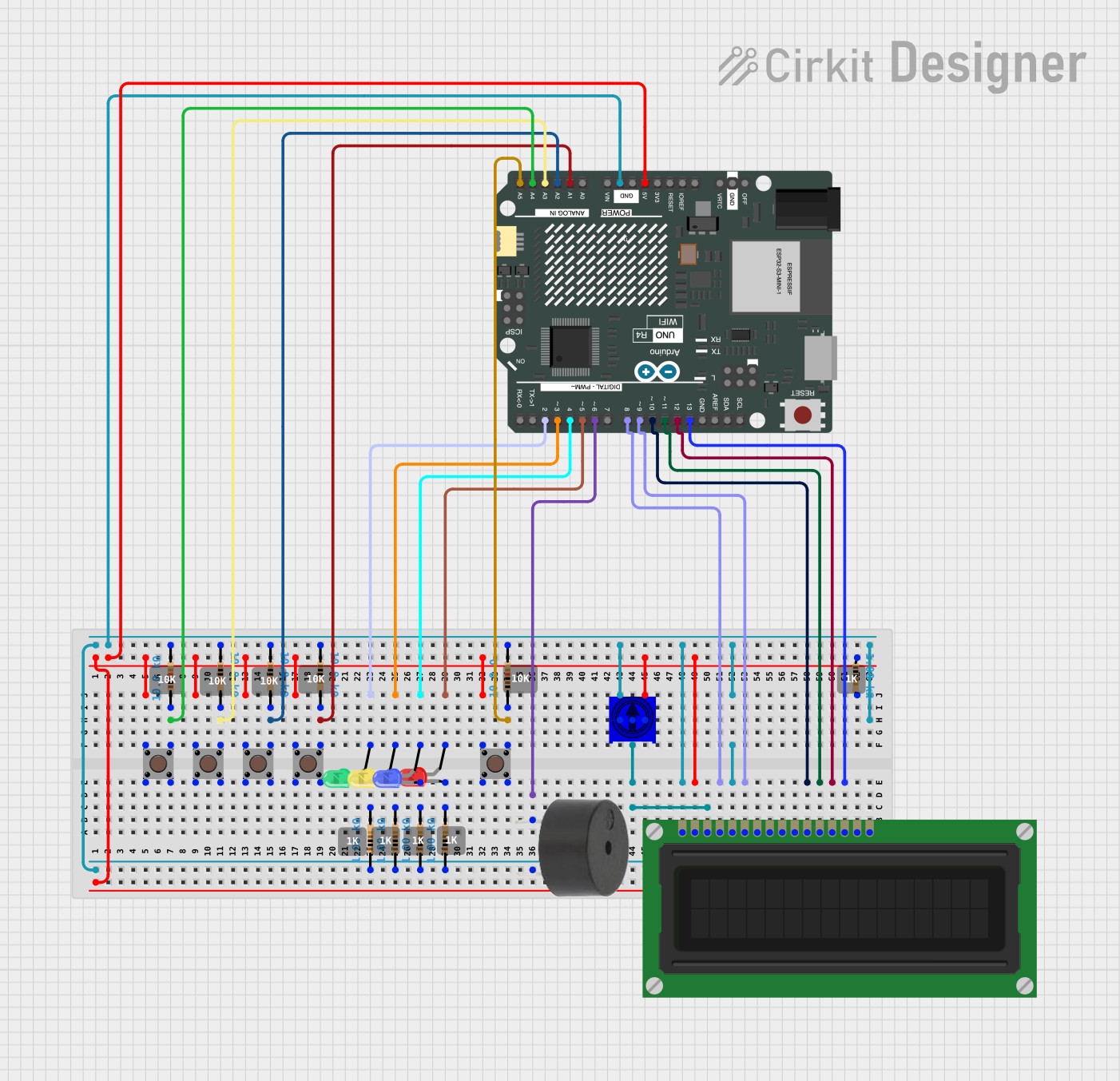
This document provides a detailed overview of a circuit designed to interface with various components including an Arduino UNO R4 WiFi, a buzzer, multiple pushbuttons, resistors, LEDs of different colors, an LCD display, and a trimming potentiometer. The circuit is powered by a 5V supply from the Arduino and includes input devices (pushbuttons), output devices (buzzer, LEDs, LCD display), and passive components (resistors, potentiometer) to form a complete interactive system.
Component List
Microcontroller
- Arduino UNO R4 WiFi: A microcontroller board based on the ATmega328, with integrated WiFi capabilities.
Input Devices
- Pushbuttons: Simple switch mechanisms for user input.
- TSR-3386UT Square Trimming Potentiometer: A variable resistor with three terminals, used to adjust LCD contrast.
Output Devices
- Buzzer: An electromechanical component that emits sound when energized.
- LEDs: Light Emitting Diodes of various colors (red, green, yellow, blue) used as indicators.
- LCD Display (16 pin): A liquid crystal display for showing alphanumeric characters.
Passive Components
- Resistors: Components used to limit current or divide voltages in the circuit. Various resistances are used, including 10 Ohms, 1000 Ohms, and 10000 Ohms.
Wiring Details
Arduino UNO R4 WiFi
- 5V and GND pins provide power to the circuit.
- Analog pins A0-A5 are connected to pushbuttons and the wiper of the potentiometer.
- Digital pins D2-D6 are connected to the LEDs and the buzzer.
- Digital pins D8-D13 are interfaced with the LCD display.
Pushbuttons
- Connected to the Arduino's analog pins through 10000 Ohm resistors.
- Also connected to the 5V supply for a pull-up configuration.
TSR-3386UT Square Trimming Potentiometer
- One leg connected to the 5V supply, the other to GND.
- The wiper adjusts the voltage at the LCD's VO pin to set the contrast.
LCD Display (16 pin)
- VDD pin connected to 5V and VSS to GND.
- RS, E, DB4-DB7 pins connected to Arduino's digital pins for data/command transfer.
- VO pin connected to the wiper of the potentiometer for contrast control.
LEDs
- Anodes connected to Arduino's digital pins D2-D5.
- Cathodes connected to GND through 1000 Ohm resistors.
Buzzer
- One pin connected to Arduino's digital pin D6.
- The other pin connected to GND.
Resistors
- Various resistors used for current limiting and pull-up configurations.
Documented Code
Arduino UNO R4 WiFi
// Code for Arduino UNO R4 WiFi is not provided in the input.
Buzzer
void setup() {
  // put your setup code here, to run once:

}

void loop() {
  // put your main code here, to run repeatedly:

}
LCD Display (16 pin)
// Code for LCD Display (16 pin) is not provided in the input.
Note: The provided code for the buzzer is a template and does not contain any functional code. The code for the Arduino UNO R4 WiFi and the LCD Display is not included in the input data.