Cirkit Designer
Your all-in-one circuit design IDE
Home /
Project Documentation
Arduino Nano-Based LCD Interface with Configurable Settings

Circuit Documentation
Summary
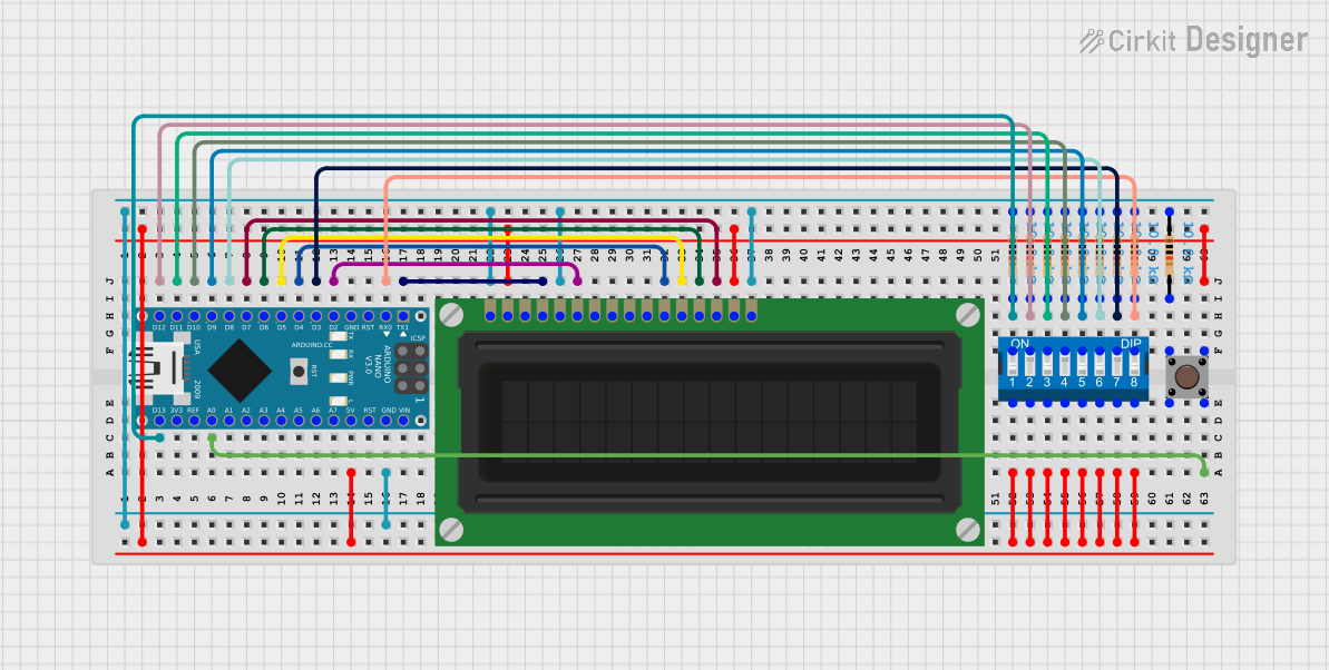
This circuit integrates an Arduino Nano microcontroller with an LCD display, a DIP switch, a pushbutton, and multiple resistors. The Arduino Nano serves as the central processing unit, controlling the LCD display and reading inputs from the DIP switch and pushbutton. The resistors are used for pull-up/pull-down configurations and current limiting purposes.
Component List
Arduino Nano
- Microcontroller board based on the ATmega328P
- Pins: D1/TX, D0/RX, RESET, GND, D2 to D13, VIN, 5V, A0 to A7, AREF, 3V3
- Purpose: Acts as the central processing unit for the circuit.
LCD Display (16 pin)
- 16-pin liquid crystal display
- Pins: VSS, VDD, VO, RS, R_W, E, DB0 to DB7, A, K
- Purpose: Displays information controlled by the Arduino Nano.
DIP Switch (8 Position)
- 8-position dual inline package switch
- Pins: 1 to 8, 9 to 16
- Purpose: Provides configurable input options to the circuit.
Pushbutton
- Standard tactile pushbutton
- Pins: Pin 1 (in), Pin 2 (in), Pin 3 (out), Pin 4 (out)
- Purpose: Serves as a user input device.
Resistor
- 10k Ohm resistors
- Pins: pin1, pin2
- Purpose: Used for pull-up/pull-down configurations and current limiting.
Wiring Details
Arduino Nano
- D13/SCK connected to DIP Switch position 16 and Resistor
- D12/MISO connected to DIP Switch position 15 and Resistor
- D11/MOSI connected to DIP Switch position 14 and Resistor
- D10 connected to DIP Switch position 13 and Resistor
- A0 connected to Pushbutton Pin 4 (out)
- D9 connected to DIP Switch position 12 and Resistor
- D8 connected to DIP Switch position 11 and Resistor
- D7 connected to LCD Display DB7
- D6 connected to LCD Display DB6
- D5 connected to LCD Display DB5
- D4 connected to LCD Display DB4
- D3 connected to DIP Switch position 10 and Resistor
- D2 connected to LCD Display E
- 5V connected to DIP Switch positions 1 to 8, LCD Display VDD, and Pushbutton Pin 3 (out)
- GND connected to all Resistor pin1, LCD Display VSS, R_W, and K
- D0/RX connected to DIP Switch position 9 and Resistor
- D1/TX connected to LCD Display RS
LCD Display (16 pin)
- DB7 to DB4 connected to Arduino Nano D7 to D4
- E connected to Arduino Nano D2
- RS connected to Arduino Nano D1/TX
- VDD connected to Arduino Nano 5V
- A connected to Arduino Nano 5V
- VSS, R_W, K connected to Arduino Nano GND
DIP Switch (8 Position)
- Positions 16 to 9 connected to Arduino Nano D13/SCK to D0/RX and respective Resistors
- Positions 1 to 8 connected to Arduino Nano 5V
Pushbutton
- Pin 4 (out) connected to Arduino Nano A0
- Pin 3 (out) connected to Arduino Nano 5V
- Pin 1 (in) connected to Resistor
Resistor
- One side (pin2) connected to various DIP Switch positions and Pushbutton Pin 1 (in)
- Other side (pin1) connected to Arduino Nano GND
Documented Code
Arduino Nano Code (sketch.ino)
void setup() {
  // put your setup code here, to run once:

}

void loop() {
  // put your main code here, to run repeatedly:

}
Additional Notes (documentation.txt)
No additional code documentation provided.