
Arduino Mega 2560 Smart Irrigation System with Sensor Integration
View and Edit Project In Cirkit Designer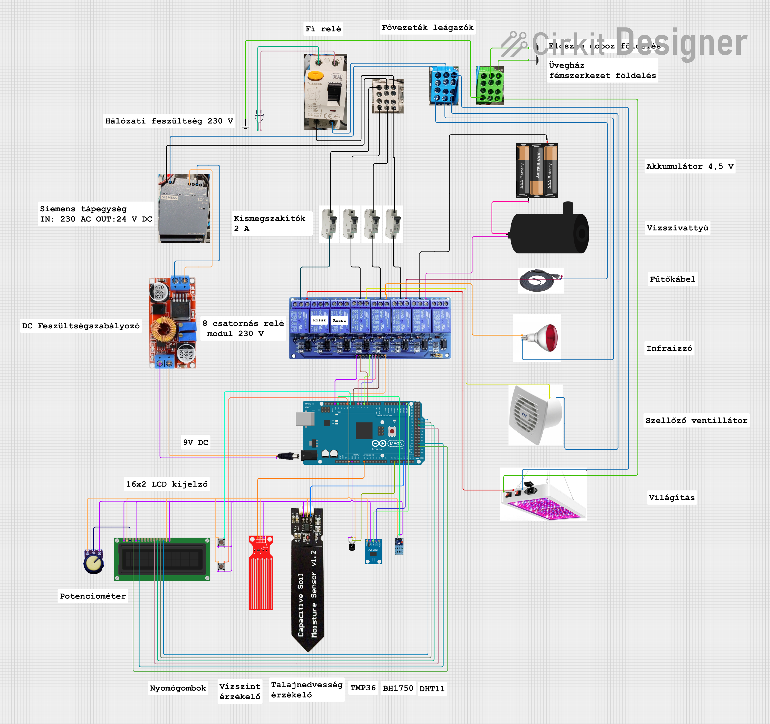
Circuit Documentation
Summary
This document provides a detailed overview of a circuit design that includes an Arduino Mega 2560 microcontroller, various sensors, relays, and other components. The circuit is designed to interface with multiple sensors and actuators, providing a comprehensive control system. The document includes a component list, wiring details, and documented code for the microcontroller.
Component List
Arduino Mega 2560
- Description: A microcontroller board based on the ATmega2560.
- Pins: IOREF, RESET, 3V3, 5V, GND, VIN, A0-A15, D0-D53, PWM, AREF, SDA, SCL
8 Channel Relay JD-VCC
- Description: A relay module with 8 channels for controlling high voltage devices.
- Pins: JD-VCC, VCC, GND, In1-In8, IN1_NC, IN1_COM, IN1_NO, IN2_NC, IN2_COM, IN2_NO, IN3_NC, IN3_COM, IN3_NO, IN4_NC, IN4_COM, IN4_NO, IN5_NC, IN5_COM, IN5_NO, IN6_NC, IN6_COM, IN6_NO, IN7_NC, IN7_COM, IN7_NO, IN8_NC, IN8_COM, IN8_NO
DHT 11
- Description: A digital temperature and humidity sensor.
- Pins: VCC, GND, DATA
BH1750
- Description: A digital light intensity sensor.
- Pins: VCC, GND, SCL, SDA, ADDR
Temperature Sensor (LM35)
- Description: An analog temperature sensor.
- Pins: +Vs, Vout, GND
Capacitive Soil Moisture Sensor V1.2
- Description: A sensor to measure soil moisture levels.
- Pins: GND, VCC, AOUT
LCD Display (16 pin)
- Description: A 16-pin LCD display for visual output.
- Pins: VSS, VDD, VO, RS, R_W, E, DB0-DB7, A, K
Pushbutton
- Description: A simple pushbutton switch.
- Pins: Pin 1 (in), Pin 2 (in), Pin 3 (out), Pin 4 (out)
Water Level Sensor
- Description: A sensor to measure water levels.
- Pins: SIG, VCC, GND
Water Pump
- Description: A pump for moving water.
- Pins: positive, negative
3xAABattery
- Description: A battery pack holding three AA batteries.
- Pins: VCC, GND
MCB
- Description: A miniature circuit breaker.
- Pins: IN, OUT
Fí Relé 2
- Description: A relay for controlling high voltage devices.
- Pins: None
Power 220v
- Description: A 220V power source.
- Pins: hot wire, neutral wire
Eloszto +, Eloszto -, Eloszto Föld
- Description: Power distribution components.
- Pins: None
GND
- Description: Ground connection.
- Pins: GND
Fűtőkábel
- Description: Heating cable.
- Pins: None
Lámpa
- Description: A lamp for illumination.
- Pins: -, +, GND
Szellőző
- Description: A ventilation fan.
- Pins: GND, +
Siemens DIN-sín tápellátás
- Description: Power supply on a DIN rail.
- Pins: +, -
Regulator Stepdown DC XL4015 CC CV
- Description: A DC-DC step-down voltage regulator.
- Pins: IN +, IN -, OUT +, OUT -
Potentiometer
- Description: A variable resistor.
- Pins: GND, Output, VCC
Power Jack
- Description: A jack for connecting power.
- Pins: POSITIF, NEGATIF
Philips Infraizzó
- Description: An infrared lamp.
- Pins: None
Wiring Details
Arduino Mega 2560
- 5V: Connected to VCC of multiple components (Temperature Sensor, LCD Display, Pushbuttons, Potentiometer, Capacitive Soil Moisture Sensor, 8 Channel Relay, BH1750, DHT 11, Water Level Sensor)
- GND: Connected to GND of multiple components (Temperature Sensor, LCD Display, Pushbuttons, Potentiometer, Capacitive Soil Moisture Sensor, 8 Channel Relay, BH1750, DHT 11, Water Level Sensor)
- A0: Connected to SIG of Water Level Sensor
- A9: Connected to Vout of Temperature Sensor
- A12: Connected to AOUT of Capacitive Soil Moisture Sensor
- D21/SCL: Connected to SCL of BH1750
- D20/SDA: Connected to SDA of BH1750
- D4 PWM: Connected to In1 of 8 Channel Relay
- D5 PWM: Connected to In4 of 8 Channel Relay
- D6 PWM: Connected to In5 of 8 Channel Relay
- D7 PWM: Connected to In6 of 8 Channel Relay
- D8 PWM: Connected to In7 of 8 Channel Relay
- D9 PWM: Connected to Pin 3 (out) of Pushbutton
- D10 PWM: Connected to Pin 3 (out) of Pushbutton
- D13 PWM: Connected to DATA of DHT 11
- D49: Connected to RS of LCD Display
- D47: Connected to E of LCD Display
- D37: Connected to DB4 of LCD Display
- D35: Connected to DB5 of LCD Display
- D33: Connected to DB6 of LCD Display
- D31: Connected to DB7 of LCD Display
8 Channel Relay JD-VCC
- VCC: Connected to 5V of Arduino Mega 2560
- GND: Connected to GND of Arduino Mega 2560
- In1: Connected to D4 PWM of Arduino Mega 2560
- In4: Connected to D5 PWM of Arduino Mega 2560
- In5: Connected to D6 PWM of Arduino Mega 2560
- In6: Connected to D7 PWM of Arduino Mega 2560
- In7: Connected to D8 PWM of Arduino Mega 2560
- IN1_COM: Connected to OUT of MCB
- IN1_NO: Connected to + of Lámpa
- IN4_COM: Connected to OUT of MCB
- IN4_NO: Connected to + of Szellőző
- IN5_COM: Connected to OUT of MCB
- IN5_NO: Connected to Philips Infraizzó
- IN6_COM: Connected to OUT of MCB
- IN6_NO: Connected to Fűtőkábel
- IN7_COM: Connected to VCC of 3xAABattery
- IN7_NO: Connected to positive of Water Pump
DHT 11
- VCC: Connected to 5V of Arduino Mega 2560
- GND: Connected to GND of Arduino Mega 2560
- DATA: Connected to D13 PWM of Arduino Mega 2560
BH1750
- VCC: Connected to 5V of Arduino Mega 2560
- GND: Connected to GND of Arduino Mega 2560
- SCL: Connected to D21/SCL of Arduino Mega 2560
- SDA: Connected to D20/SDA of Arduino Mega 2560
Temperature Sensor (LM35)
- +Vs: Connected to 5V of Arduino Mega 2560
- Vout: Connected to A9 of Arduino Mega 2560
- GND: Connected to GND of Arduino Mega 2560
Capacitive Soil Moisture Sensor V1.2
- GND: Connected to GND of Arduino Mega 2560
- VCC: Connected to 5V of Arduino Mega 2560
- AOUT: Connected to A12 of Arduino Mega 2560
LCD Display (16 pin)
- VSS: Connected to GND of Arduino Mega 2560
- VDD: Connected to 5V of Arduino Mega 2560
- VO: Connected to Output of Potentiometer
- RS: Connected to D49 of Arduino Mega 2560
- R_W: Connected to GND of Arduino Mega 2560
- E: Connected to D47 of Arduino Mega 2560
- DB4: Connected to D37 of Arduino Mega 2560
- DB5: Connected to D35 of Arduino Mega 2560
- DB6: Connected to D33 of Arduino Mega 2560
- DB7: Connected to D31 of Arduino Mega 2560
- A: Connected to