
ESP8266 NodeMCU RFID Access Control with LCD Feedback and Alert Indicators
View and Edit Project In Cirkit Designer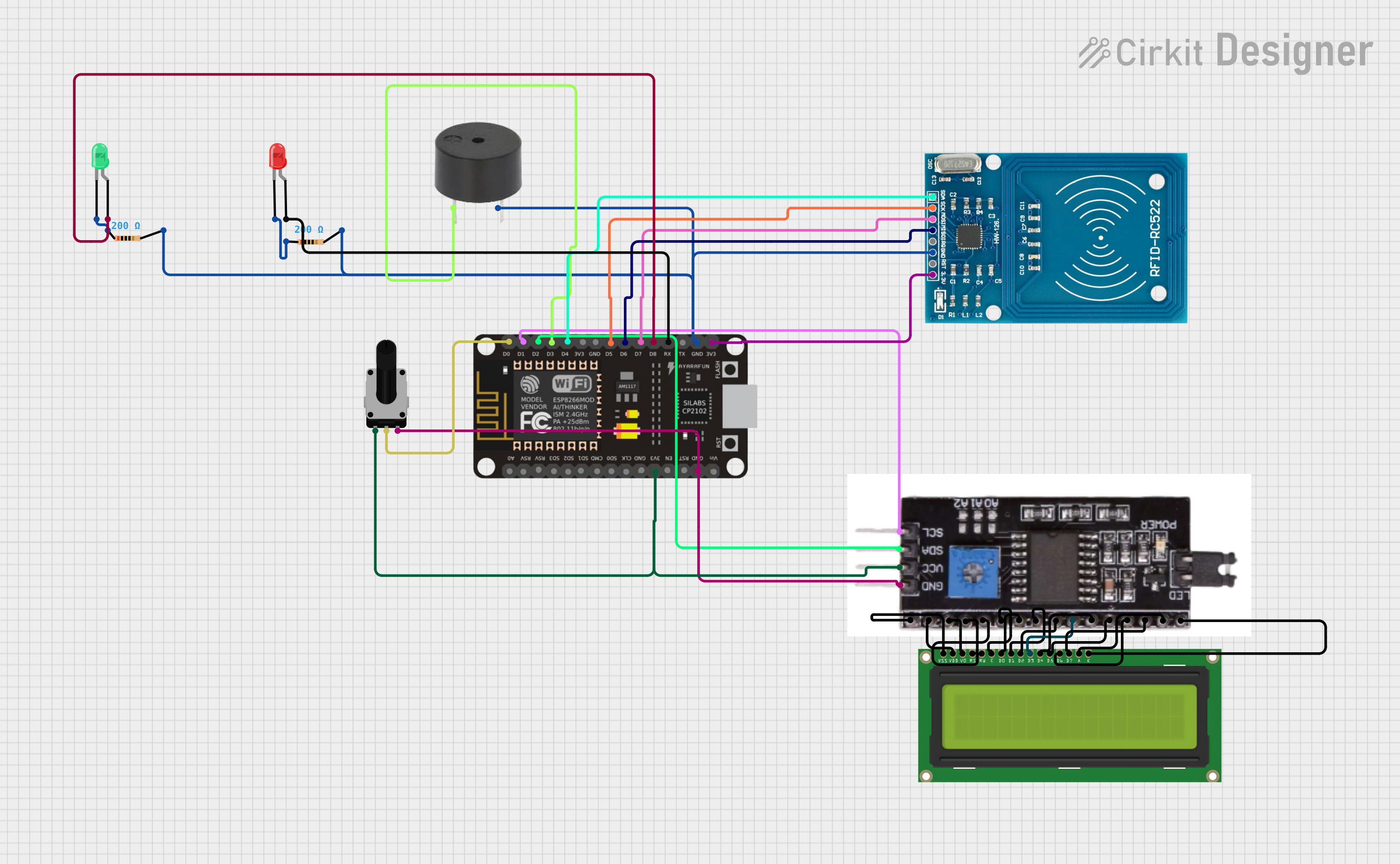
Circuit Documentation
Summary
This circuit integrates various components controlled by an ESP8266 NodeMCU microcontroller. The circuit includes an RFID-RC522 module for RFID communication, a 16x2 LCD display interfaced via an I2C module for user feedback, two LEDs (green and red) for status indication, a buzzer for audio alerts, and a rotary potentiometer for user input. The circuit is designed to operate on a 3.3V power supply, which is provided by the ESP8266 NodeMCU. The components are interconnected through a series of electrical nets, ensuring communication and control between the microcontroller and peripherals.
Component List
ESP8266 NodeMCU
- Microcontroller with WiFi capability
- Pins: D0-D8, RX, TX, A0, RSV, SD3, SD2, SD1, CMD, SD0, CLK, EN, RST, VIN, 3V3, GND
RFID-RC522
- RFID reader/writer module
- Pins: VCC (3.3V), RST, GND, IRQ, MISO, MOSI, SCK, SDA
LCD Display 16x2
- Alphanumeric liquid crystal display
- Pins: LEDK, LEDA, DB7-DB0, E, RW, RS, VO, VDD, VSS
LED: Two Pin (green)
- Green light-emitting diode
- Pins: cathode, anode
LED: Two Pin (red)
- Red light-emitting diode
- Pins: cathode, anode
Buzzer
- Audio signaling device
- Pins: PIN, GND
Resistor (200 Ohms)
- Two resistors with 200 Ohms resistance each
- Pins: pin1, pin2
I2C Module
- Interface module for LCD display
- Pins: VSS, VO, RS, RW, E, DB7-DB0, LEDA, LEDK, GND, VCC, SDA, SCL, VDD
Rotary Potentiometer (10k Ohms)
- Variable resistor with three terminals
- Pins: leg1, wiper, leg2
Wiring Details
ESP8266 NodeMCU
- D0 connected to Rotary Potentiometer wiper
- D1 (SCL) connected to I2C Module SCL
- D2 (SDA) connected to I2C Module SDA
- D3 connected to Buzzer PIN
- D4 connected to RFID-RC522 SDA
- D5 connected to RFID-RC522 SCK
- D6 connected to RFID-RC522 MISO
- D7 connected to RFID-RC522 MOSI
- D8 connected to Green LED anode
- RX connected to Red LED anode
- GND connected to common ground net
- 3V3 connected to common 3.3V power net
RFID-RC522
- SDA, SCK, MISO, MOSI connected to corresponding ESP8266 NodeMCU pins
- GND connected to common ground net
- VCC (3.3V) connected to common 3.3V power net
LCD Display 16x2
- Interfaced via I2C Module, all control and data pins connected to corresponding I2C Module pins
LED: Two Pin (green)
- Anode connected to ESP8266 NodeMCU D8
- Cathode connected to 200 Ohm Resistor pin1
LED: Two Pin (red)
- Anode connected to ESP8266 NodeMCU RX
- Cathode connected to 200 Ohm Resistor pin1
Buzzer
- PIN connected to ESP8266 NodeMCU D3
- GND connected to common ground net
Resistor (200 Ohms)
- Two resistors each with one pin connected to the cathode of the green and red LEDs respectively, and the other pin connected to common ground net
I2C Module
- SCL, SDA connected to ESP8266 NodeMCU D1 and D2 respectively
- LEDA, LEDK, DB7-DB0, E, RW, RS, VO, VDD, VSS connected to corresponding LCD Display 16x2 pins
- GND connected to common ground net
- VCC connected to common 3.3V power net
Rotary Potentiometer (10k Ohms)
- Wiper connected to ESP8266 NodeMCU D0
- Leg1 connected to common 3.3V power net
- Leg2 connected to common ground net
Documented Code
No code has been provided for the microcontroller. The code would typically initialize the peripherals, handle the communication with the RFID module, update the LCD display, and manage the status LEDs and buzzer based on the system state and user input from the rotary potentiometer.