
Arduino 101 Based RFID and GSM Security System with I2C LCD Display and RTC
View and Edit Project In Cirkit Designer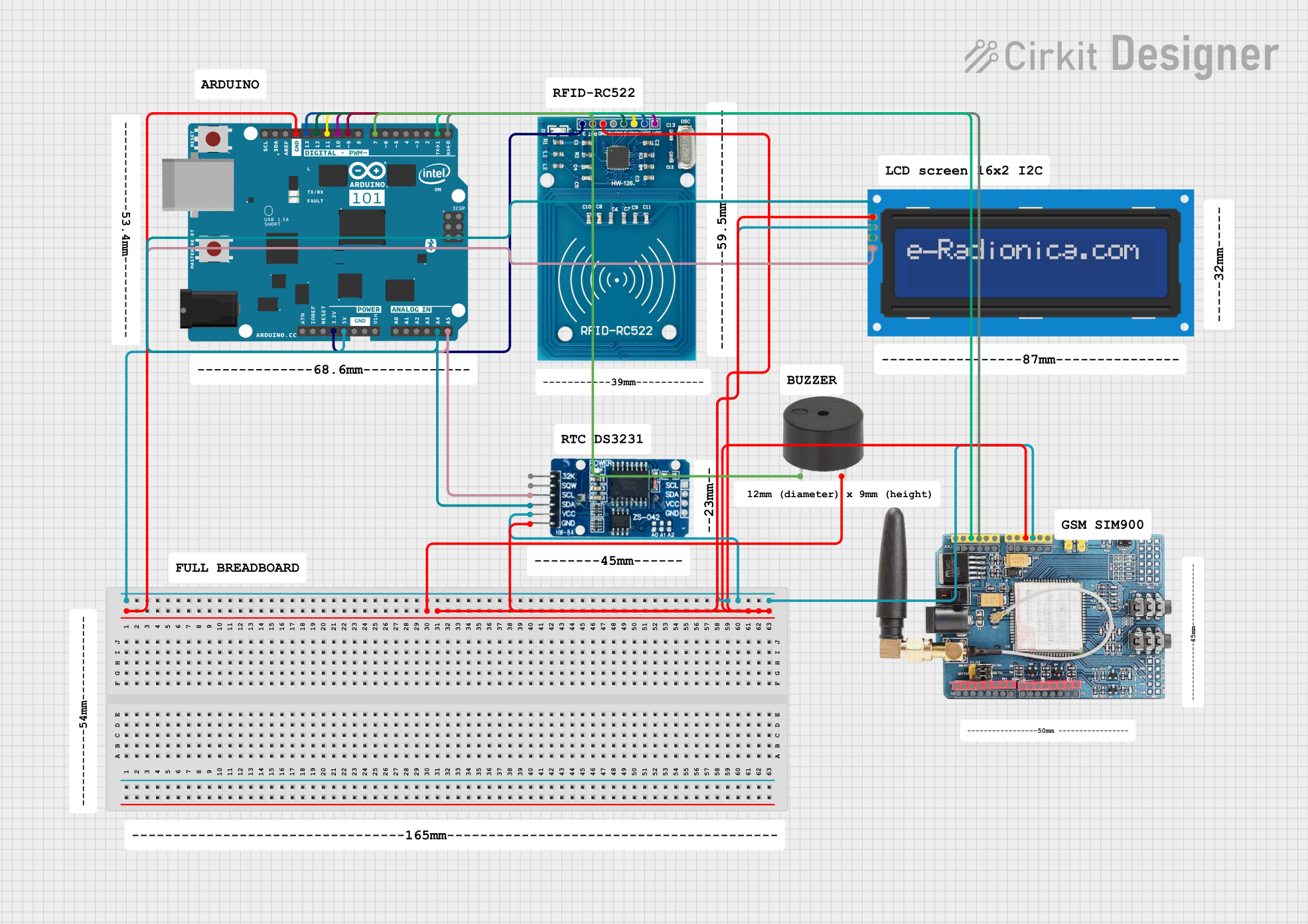
Circuit Documentation
Summary
The circuit in question is designed to interface an Arduino 101 microcontroller with several peripheral devices, including an RFID-RC522 module for RFID communication, a GSM SIM900 module for cellular connectivity, a buzzer for audio signaling, an RTC DS3231 module for real-time clock capabilities, and an LCD screen with I2C interface for display purposes. The circuit is powered by the Arduino 101's 5V and 3.3V outputs and uses various digital and analog pins for communication between the microcontroller and the peripherals.
Component List
Arduino 101
- Microcontroller board based on the Intel Curie module.
- Provides 5V and 3.3V power outputs and multiple digital and analog I/O pins.
- Used as the central processing unit of the circuit.
RFID-RC522
- RFID reader/writer module operating at 13.56 MHz.
- Interfaces with the Arduino 101 for RFID tag reading and writing.
GSM SIM900
- GSM/GPRS module for cellular communication.
- Allows the circuit to send SMS, make calls, and use the internet over a mobile network.
Buzzer
- An electromechanical component that produces sound.
- Used for audio alerts or signals.
RTC DS3231
- A real-time clock module for timekeeping.
- Maintains accurate time with a battery backup.
LCD Screen 16x2 I2C
- An alphanumeric liquid crystal display with 16 characters by 2 lines.
- Features an I2C interface for communication with the Arduino 101.
Wiring Details
Arduino 101
- GND: Connected to the ground pins of all other components.
- 5V: Provides power to the LCD screen, RTC DS3231, and GSM SIM900.
- 3V3: Powers the RFID-RC522 module.
- A5/SCL: Connected to the SCL pins of the LCD screen and RTC DS3231 for I2C communication.
- A4/SDA: Connected to the SDA pins of the LCD screen and RTC DS3231 for I2C communication.
- D9 PWM: Connected to the RST pin of the RFID-RC522 for reset control.
- D12/MISO: Connected to the MISO pin of the RFID-RC522 for SPI communication.
- D11 PWM/MOSI: Connected to the MOSI pin of the RFID-RC522 for SPI communication.
- D13/SCK: Connected to the SCK pin of the RFID-RC522 for SPI communication.
- D10 PWM/SS: Connected to the SDA pin of the RFID-RC522 for SPI communication.
- D7: Connected to the PIN of the buzzer for control.
- D1/TX: Connected to the A3 pin of the GSM SIM900 for serial communication.
- D0/RX: Connected to the A2 pin of the GSM SIM900 for serial communication.
RFID-RC522
- VCC (3.3V): Powered by the 3.3V output from the Arduino 101.
- RST: Reset control via D9 PWM on the Arduino 101.
- GND: Ground connection.
- MISO: SPI communication with D12/MISO on the Arduino 101.
- MOSI: SPI communication with D11 PWM/MOSI on the Arduino 101.
- SCK: SPI communication with D13/SCK on the Arduino 101.
- SDA: SPI communication with D10 PWM/SS on the Arduino 101.
GSM SIM900
- 5V: Powered by the 5V output from the Arduino 101.
- GND: Ground connection.
- A3: Serial communication with D1/TX on the Arduino 101.
- A2: Serial communication with D0/RX on the Arduino 101.
Buzzer
- PIN: Controlled by D7 on the Arduino 101.
- GND: Ground connection.
RTC DS3231
- VCC: Powered by the 5V output from the Arduino 101.
- GND: Ground connection.
- SCL: I2C communication with A5/SCL on the Arduino 101.
- SDA: I2C communication with A4/SDA on the Arduino 101.
LCD Screen 16x2 I2C
- VCC: Powered by the 5V output from the Arduino 101.
- GND: Ground connection.
- SCL: I2C communication with A5/SCL on the Arduino 101.
- SDA: I2C communication with A4/SDA on the Arduino 101.
Documented Code
No code has been provided for the microcontroller. The documentation of the code would typically include setup routines, main program logic, function definitions, and comments explaining the purpose and functionality of each section of the code. Since no code is available, this section cannot be completed. If code becomes available, it should be documented here following best practices for code documentation, including descriptions of the purpose of the code, the functionality of different parts, and how the code interacts with the hardware components listed above.