AC Bulb Control Circuit with Flush Switch and MCB Protection
Circuit Documentation
Summary of the Circuit
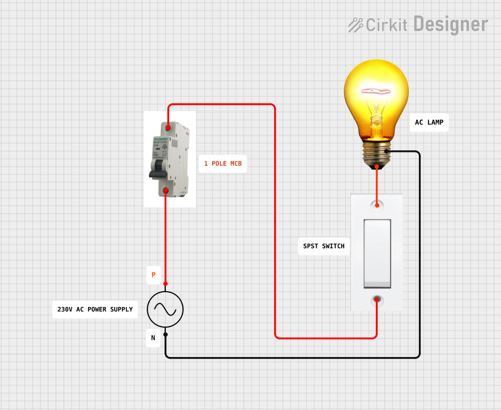
The circuit described by the provided inputs is a simple AC power control circuit that uses a manual flush switch to control an AC bulb. The circuit is powered by an AC supply and includes a Miniature Circuit Breaker (MCB) for safety, which protects the circuit from overcurrent conditions. The flush switch acts as an interface for the user to turn the AC bulb on and off. There is no microcontroller or embedded code involved in this circuit.
Component List
Flush Switch
- Description: A manual switch used to open or close the electrical circuit.
- Pins: GND, VCC
- Purpose: To control the power to the AC bulb.
AC Bulb
- Description: A light-emitting component that operates on AC power.
- Pins: P (Phase), N (Neutral)
- Purpose: To provide illumination when powered.
AC Supply
- Description: The source of alternating current (AC) power for the circuit.
- Pins: +ve (Live), -ve (Neutral)
- Purpose: To supply electrical power to the circuit.
MCB (Miniature Circuit Breaker)
- Description: A safety device that automatically cuts off the electrical power in case of an overload or short circuit.
- Pins: IN, OUT
- Purpose: To protect the circuit from overcurrent conditions.
Comments
- Description: Placeholder components that may represent annotations or notes in the circuit design. These components do not have electrical functionality.
Wiring Details
Flush Switch
- GND: Connected to the OUT pin of the MCB.
- VCC: Connected to the P pin of the AC Bulb.
AC Bulb
- P: Connected to the VCC pin of the Flush Switch.
- N: Connected to the -ve pin of the AC Supply.
AC Supply
- +ve: Connected to the IN pin of the MCB.
- -ve: Connected to the N pin of the AC Bulb.
MCB
- IN: Connected to the +ve pin of the AC Supply.
- OUT: Connected to the GND pin of the Flush Switch.
Documented Code
There is no microcontroller or embedded code associated with this circuit. Therefore, this section is not applicable.
This documentation provides an overview of the circuit's components, their purpose, and how they are wired together. The circuit is straightforward and does not include any programmable devices or software control.