Cirkit Designer
Your all-in-one circuit design IDE
Home /
Project Documentation
Arduino UNO Based Sound Detection System with MAX4466 Microphone Amplifier and LM358 Op-Amp

Circuit Documentation
Summary
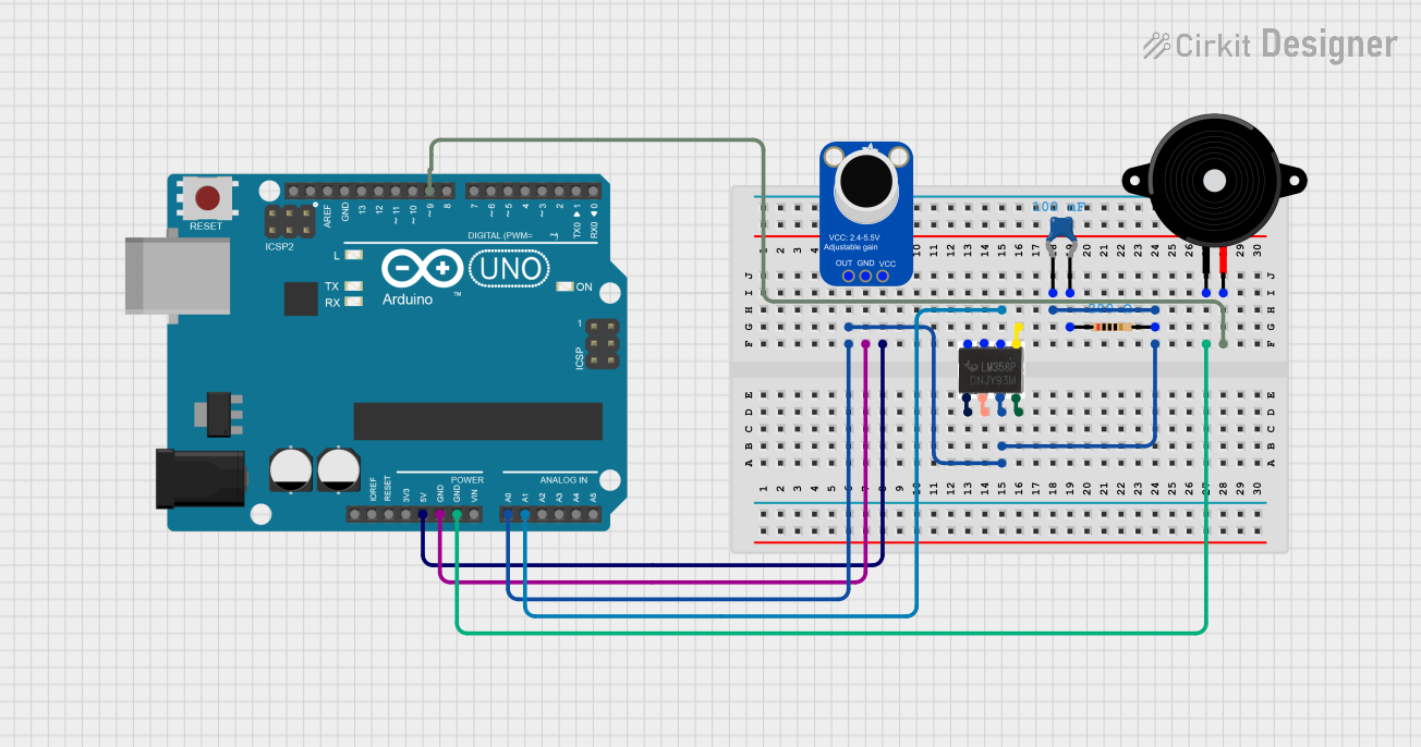
This circuit appears to be designed for audio signal processing and output. It includes an Arduino UNO microcontroller for control logic, an Adafruit MAX4466 Electret Microphone Amplifier for capturing audio signals, an LM358 Op-Amp for signal amplification, a resistor and a ceramic capacitor for filtering, and a Piezo Speaker for audio output.
Component List
Arduino UNO
- Microcontroller board based on the ATmega328P
- It has 14 digital input/output pins, 6 analog inputs, a 16 MHz quartz crystal, a USB connection, a power jack, an ICSP header, and a reset button.
Adafruit MAX4466 Electret Microphone Amplifier
- An adjustable gain microphone amplifier with an electret microphone input and an output to send the amplified signal to another device.
LM358 Op-Amp
- A dual operational amplifier chip that can be used for signal amplification, filtering, or other analog functions.
Resistor
- A passive two-terminal electrical component that implements electrical resistance as a circuit element.
- Resistance: 200 Ohms
Ceramic Capacitor
- A fixed-value capacitor where the ceramic material acts as the dielectric.
- Capacitance: 0.1 µF (100 nF)
Piezo Speaker
- An electronic device that emits sound when an electric current passes through it.
Wiring Details
Arduino UNO
A0connected to the output of the signal processing chain (LM358 Op-Amp pin 3)GNDconnected to the ground of Adafruit MAX4466 and Piezo Speaker5Vconnected to the VCC of Adafruit MAX4466A1connected to LM358 Op-Amp pin 6D9connected to one terminal of the Piezo Speaker
Adafruit MAX4466 Electret Microphone Amplifier
OUTconnected to the input of the signal processing chain (LM358 Op-Amp pin 3)GNDconnected to the ground of Arduino UNOVCCconnected to the 5V output of Arduino UNO
LM358 Op-Amp
- Pin
3connected to the output of Adafruit MAX4466 and input of Arduino UNOA0 - Pin
6connected to Arduino UNOA1 - Other pins (
1,2,4,5) are not connected in the provided net list and may be used for other functions or left unconnected.
Resistor
- One terminal (
pin1) connected to one terminal of the Ceramic Capacitor - The other terminal (
pin2) connected to the output of Adafruit MAX4466 and input of LM358 Op-Amp pin 3
Ceramic Capacitor
- One terminal (
pin0) connected to the output of Adafruit MAX4466 and input of LM358 Op-Amp pin 3 - The other terminal (
pin1) connected to one terminal of the Resistor
Piezo Speaker
- One terminal (
pin1) connected to the ground of Arduino UNO - The other terminal (
pin2) connected to the digital outputD9of Arduino UNO
Documented Code
Arduino UNO - sketch.ino
void setup() {
  // put your setup code here, to run once:

}

void loop() {
  // put your main code here, to run repeatedly:

}
Arduino UNO - documentation.txt
(No additional documentation provided for the code)
This documentation provides an overview of the circuit components, their connections, and the initial code structure for the Arduino UNO. Further details may be required for a complete understanding of the circuit's functionality, such as the specific operations performed by the LM358 Op-Amp and the intended behavior of the Arduino code.