
Satellite Compass and Network-Integrated GPS Data Processing System
View and Edit Project In Cirkit Designer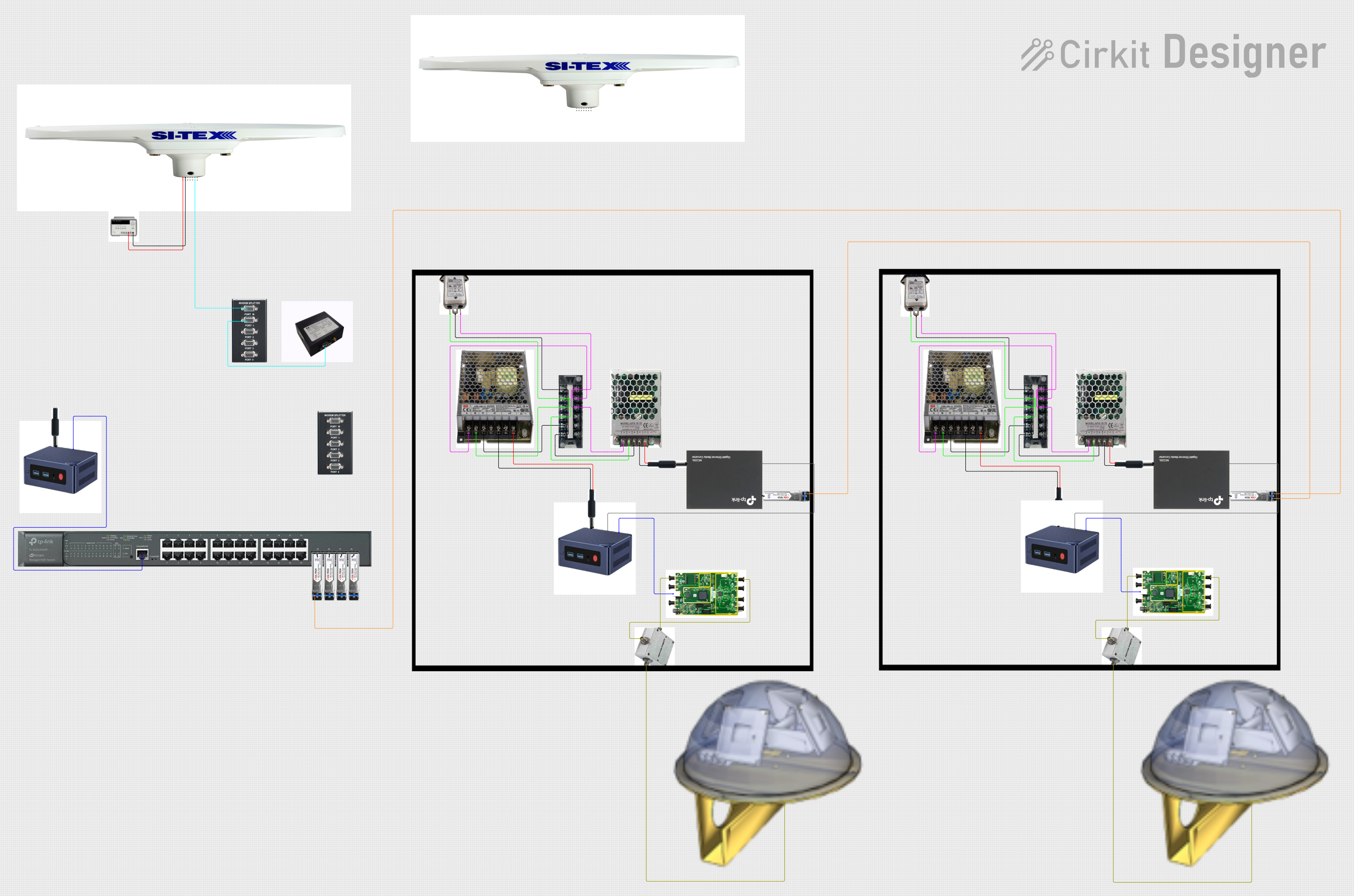
Circuit Documentation
Summary
The circuit in question appears to be a complex system involving power supply units, data communication modules, a satellite compass, network devices, and various connectors. The system is designed to handle both power distribution and data transmission, with specific components dedicated to GPS functionality, Ethernet communication, and RF signal processing. The circuit does not include any embedded code for microcontrollers.
Component List
Power Supply Components
- Triple Output DC Power Supply: Provides multiple voltage outputs, including a 25V supply used in this circuit.
- SMPS_LRS-100-12: A switch-mode power supply that converts AC to 12V DC output.
- SMPS_9V_UP15S09: Another switch-mode power supply that provides a 9V DC output.
- 5.5mm * 2.1mm DC jack: A DC power jack used to supply power to various components.
Data Communication Components
- SI-TEX G1 Satellite Compass: A satellite compass with multiple communication ports, including RS-232 and RS-422.
- Beelink MINI S12 N95: A mini PC with USB and HDMI outputs, as well as a Gigabit Ethernet NIC.
- Ettus USRP B200: A software-defined radio platform with USB connectivity and SMA connectors for antennas.
- 1000BASE-T Media Converter MC220L: A media converter that provides an SFP port for fiber optic connections and a Gigabit Ethernet port.
- TP-LINK TL-SG3428XMP 24 port Network Switch: A network switch with PoE capabilities and SFP ports for fiber optic connections.
RF and GPS Components
- TAE ANT: An antenna with an SMA output.
- RF Directional Coupler: A component used in RF applications to couple a certain amount of electromagnetic power.
- XHTF1021 Atomic rubidium Clock: A high-precision clock with 1pps input and output.
Connectors and Signal Processing
- RS232 Splitter: A device that splits RS232 signals to multiple outputs.
- Duplex LC connector SFP-LX20: A fiber optic connector for single-mode fiber with LC-type connectors.
- Terminal Block KTB1 20A 6P: A terminal block for connecting and distributing electrical power.
Miscellaneous
- AC Filter_CW10A: An AC power line filter for electromagnetic interference suppression.
- CASE: Enclosures for housing and protecting electronic components.
Wiring Details
Power Supply Wiring
Triple Output DC Power Supply
25V +to SI-TEX G1 Satellite CompassRED: Power input (8 to 40VDC)25V -to SI-TEX G1 Satellite CompassBlack: Power ground
SMPS_LRS-100-12
L: LiveandN: Neutralconnected to AC Filter_CW10A and Terminal Block KTB1 20A 6P-Vto 5.5mm * 2.1mm DC jackBlack: Negative Pole+Vto 5.5mm * 2.1mm DC jackRED: Positive Pole
SMPS_9V_UP15S09
Neutral,Live, andGNDconnected to AC Filter_CW10A and Terminal Block KTB1 20A 6P-Vto 5.5mm * 2.1mm DC jackBlack: Negative Pole+Vto 5.5mm * 2.1mm DC jackRED: Positive Pole
Data Communication Wiring
SI-TEX G1 Satellite Compass
Orange: 1pulse per second + (1 PPS +)to RS232 SplitterM6
Beelink MINI S12 N95
Power: Input 100-240V AC, 50/60Hz, Output 12V/3Aconnected to 5.5mm * 2.1mm DC jacksUSB 3: USB3.2 Gen2(10Gbps)to Ettus USRP B200USB3.0: USB date, PowerLAN: 1x RealTek RTL8168/8111 PCI-E Gigabit Ethernet NICto 1000BASE-T Media Converter MC220L1000BASE-T
Ettus USRP B200
SMA: TX/RX, Main Transmit/ReceiveandSMA: GPS Antennaconnected to RF Directional CouplerCoupledandInput, respectively
1000BASE-T Media Converter MC220L
SFPconnected to Duplex LC connector SFP-LX20LAN
TP-LINK TL-SG3428XMP 24 port Network Switch
RJ45 Consoleconnected to Beelink MINI S12 N95LAN: 1x RealTek RTL8168/8111 PCI-E Gigabit Ethernet NIC25: SFP,26: SFP,27: SFP,28: SFPconnected to Duplex LC connector SFP-LX20LAN
RF and GPS Wiring
RF Directional Coupler
Outputconnected to TAE ANTSMA: ANT Output
XHTF1021 Atomic rubidium Clock
6: NC or 1pps inputto RS232 Splitter16
Fiber Optic Wiring
- Duplex LC connector SFP-LX20
Optic LC type Single Mode: RxandOptic LC type Single Mode: Txinterconnected between different instances
Documented Code
No code has been provided for microcontrollers or other programmable devices in the circuit. Therefore, this section is not applicable to the current documentation.