
Arduino Nano and TB6600 Stepper Motor Driver Joystick-Controlled System
View and Edit Project In Cirkit Designer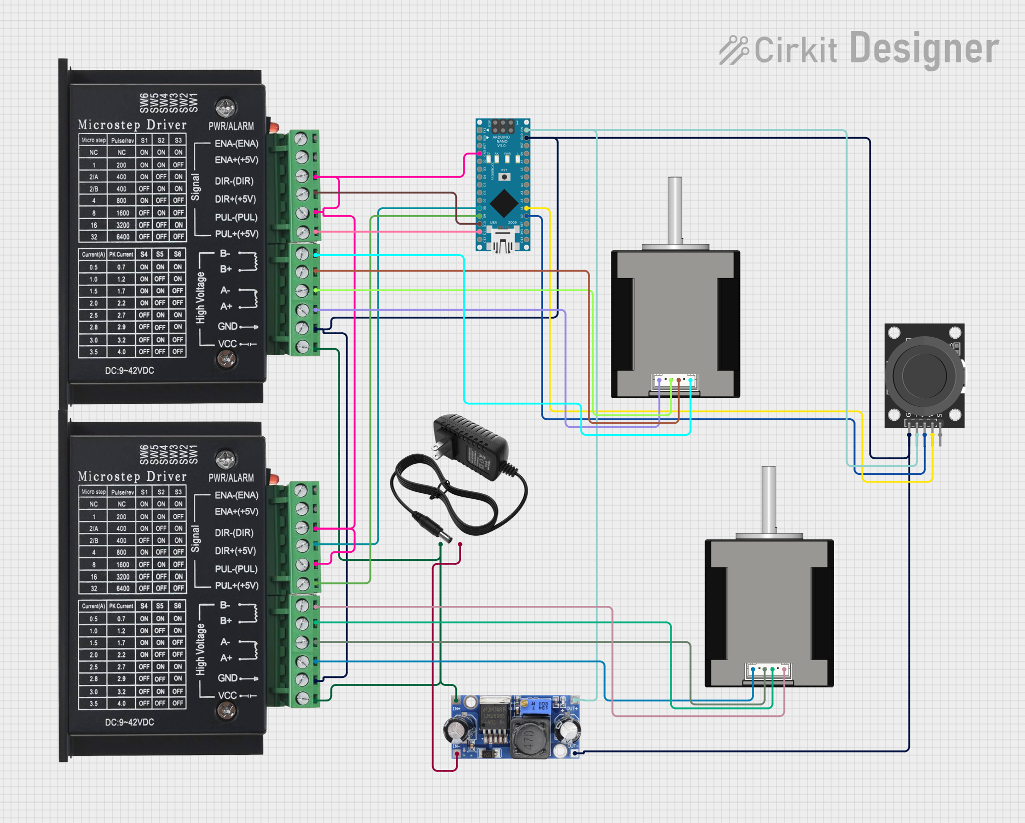
Circuit Documentation
Summary
This circuit is designed to control two TB6600 stepper motor drivers using an Arduino Nano and a KY-023 Dual Axis Joystick Module. The joystick controls the direction and speed of the stepper motors. The circuit is powered by a 12V power supply, and a DC-DC converter is used to step down the voltage for the Arduino Nano and other components.
Component List
TB6600 Stepper Motor Driver
- Description: A stepper motor driver capable of driving a Nema 17 stepper motor.
- Pins: ENA-, ENA+, DIR-, DIR+, PUL-, PUL+, B-, B+, A-, A+, GND, VCC
Arduino Nano
- Description: A small, complete, and breadboard-friendly board based on the ATmega328P.
- Pins: D1/TX, D0/RX, RESET, GND, D2, D3, D4, D5, D6, D7, D8, D9, D10, D11/MOSI, D12/MISO, VIN, 5V, A7, A6, A5, A4, A3, A2, A1, A0, AREF, 3V3, D13/SCK
KY-023 Dual Axis Joystick Module
- Description: A joystick module with two potentiometers for X and Y axis control and a push button.
- Pins: GND, +5V, VRx, VRy, SW
Nema 17 42-STH48 Stepper Motor
- Description: A bipolar stepper motor commonly used in 3D printers and CNC machines.
- Pins: A2 (black), A1 (green), B2 (red), B1 (blue)
12V Power Supply
- Description: A power supply providing 12V DC output.
- Pins: +, -
DC-DC Converter
- Description: A voltage converter to step down 12V to 5V.
- Pins: +VCC IN, GND IN, +VCC OUT, GND OUT
Wiring Details
TB6600 Stepper Motor Driver 1
- DIR-: Connected to GND of Arduino Nano
- PUL-: Connected to GND of Arduino Nano
- DIR+: Connected to D10 of Arduino Nano
- PUL+: Connected to D11/MOSI of Arduino Nano
- B-: Connected to B1 Blue of Nema 17 Stepper Motor 1
- B+: Connected to B2 Red of Nema 17 Stepper Motor 1
- A-: Connected to A1 Green of Nema 17 Stepper Motor 1
- A+: Connected to A2 (black) of Nema 17 Stepper Motor 1
- GND: Connected to GND of Arduino Nano, GND of KY-023 Joystick, and GND OUT of DC-DC Converter
- VCC: Connected to +VCC IN of DC-DC Converter
TB6600 Stepper Motor Driver 2
- DIR-: Connected to GND of Arduino Nano
- PUL-: Connected to GND of Arduino Nano
- DIR+: Connected to D8 of Arduino Nano
- PUL+: Connected to D9 of Arduino Nano
- B-: Connected to B1 Blue of Nema 17 Stepper Motor 2
- B+: Connected to B2 Red of Nema 17 Stepper Motor 2
- A-: Connected to A1 Green of Nema 17 Stepper Motor 2
- A+: Connected to A2 (black) of Nema 17 Stepper Motor 2
- GND: Connected to GND of Arduino Nano, GND of KY-023 Joystick, and GND OUT of DC-DC Converter
- VCC: Connected to +VCC IN of DC-DC Converter
Arduino Nano
- GND: Connected to GND of TB6600 Stepper Motor Driver 1, GND of TB6600 Stepper Motor Driver 2, GND of KY-023 Joystick, and GND OUT of DC-DC Converter
- D10: Connected to DIR+ of TB6600 Stepper Motor Driver 1
- D11/MOSI: Connected to PUL+ of TB6600 Stepper Motor Driver 1
- D8: Connected to DIR+ of TB6600 Stepper Motor Driver 2
- D9: Connected to PUL+ of TB6600 Stepper Motor Driver 2
- VIN: Connected to +5V of KY-023 Joystick and +VCC OUT of DC-DC Converter
- A0: Connected to VRx of KY-023 Joystick
- A1: Connected to VRy of KY-023 Joystick
KY-023 Dual Axis Joystick Module
- GND: Connected to GND of Arduino Nano
- +5V: Connected to VIN of Arduino Nano and +VCC OUT of DC-DC Converter
- VRx: Connected to A0 of Arduino Nano
- VRy: Connected to A1 of Arduino Nano
Nema 17 42-STH48 Stepper Motor 1
- B1 Blue: Connected to B- of TB6600 Stepper Motor Driver 1
- B2 Red: Connected to B+ of TB6600 Stepper Motor Driver 1
- A1 Green: Connected to A- of TB6600 Stepper Motor Driver 1
- A2 (black): Connected to A+ of TB6600 Stepper Motor Driver 1
Nema 17 42-STH48 Stepper Motor 2
- B1 Blue: Connected to B- of TB6600 Stepper Motor Driver 2
- B2 Red: Connected to B+ of TB6600 Stepper Motor Driver 2
- A1 Green: Connected to A- of TB6600 Stepper Motor Driver 2
- A2 (black): Connected to A+ of TB6600 Stepper Motor Driver 2
12V Power Supply
- +: Connected to +VCC IN of DC-DC Converter and VCC of TB6600 Stepper Motor Driver 1 and 2
- -: Connected to GND IN of DC-DC Converter
DC-DC Converter
- +VCC IN: Connected to + of 12V Power Supply
- GND IN: Connected to - of 12V Power Supply
- +VCC OUT: Connected to VIN of Arduino Nano and +5V of KY-023 Joystick
- GND OUT: Connected to GND of Arduino Nano, GND of KY-023 Joystick, and GND of TB6600 Stepper Motor Driver 1 and 2
Code Documentation
/*
 * Arduino Sketch for controlling two TB6600 stepper motor drivers using
 * an Arduino Nano and a KY-023 Dual Axis Joystick Module. The joystick
 * controls the direction and speed of the stepper motors.
 */

// Pin definitions
const int joystickVRx = A0;
const int joystickVRy = A1;
const int stepper1DirPin = 10;
const int stepper1StepPin = 11;
const int stepper2DirPin = 8;
const int stepper2StepPin = 9;

void setup() {
  // Initialize serial communication
  Serial.begin(9600);

  // Set pin modes for stepper motor control
  pinMode(stepper1DirPin, OUTPUT);
  pinMode(stepper1StepPin, OUTPUT);
  pinMode(stepper2DirPin, OUTPUT);
  pinMode(stepper2StepPin, OUTPUT);
}

void loop() {
  // Read joystick values
  int xValue = analogRead(joystickVRx);
  int yValue = analogRead(joystickVRy);

  // Map joystick values to stepper motor control
  int stepper1Speed = map(xValue, 0, 1023, 0, 255);
  int stepper2Speed = map(yValue, 0, 1023, 0, 255);

  // Control stepper motor 1
  if (xValue < 512) {
    digitalWrite(stepper1DirPin, LOW); // Set direction
  } else {
    digitalWrite(stepper1DirPin, HIGH); // Set direction
  }
  for (int i = 0; i < stepper1Speed; i++) {
    digitalWrite(stepper1StepPin, HIGH);
    delayMicroseconds(1000);
    digitalWrite(stepper1StepPin, LOW);
    delayMicroseconds(1000);
  }

  // Control stepper motor 2
  if (yValue < 512) {
    digitalWrite(stepper2DirPin, LOW); // Set direction
  } else