ESP32-Based Sensor Integration and Motor Control System
Circuit Documentation
Summary
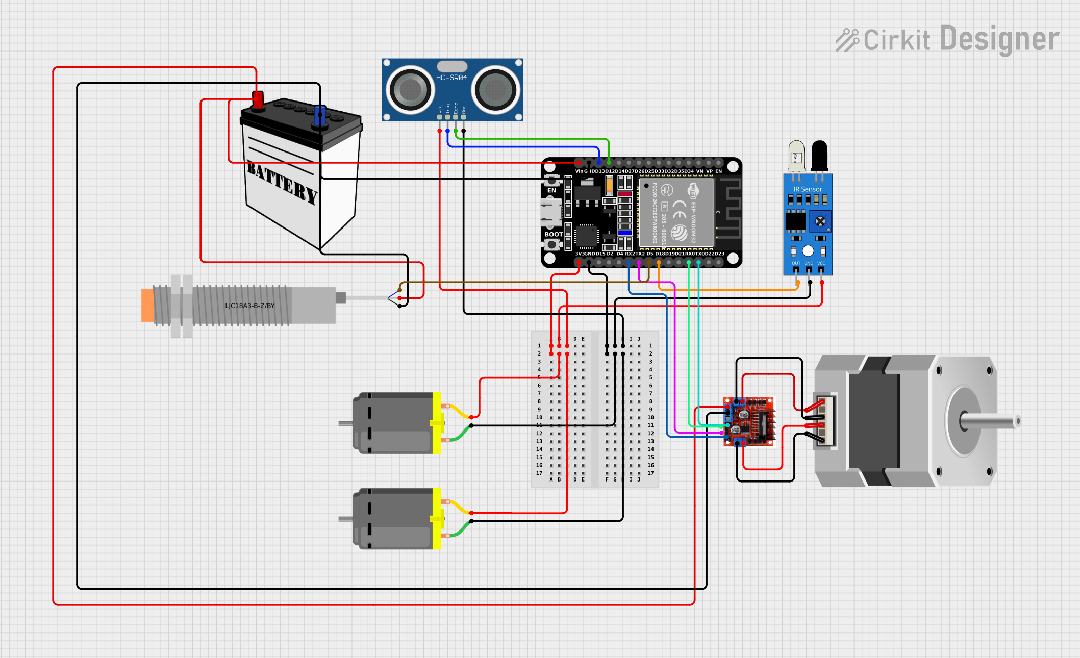
The circuit in question appears to be a complex system involving a microcontroller, sensors, motor drivers, and actuators. The central processing unit is an ESP32 microcontroller, which interfaces with an IR sensor, an ultrasonic sensor (HC-SR04), a capacitive proximity sensor (LJC18A3-B-Z/BY), and controls a stepper motor, two DC motors through an L298N motor driver. The system is powered by a 12V battery, and the ESP32 microcontroller regulates the power distribution to the sensors and DC motors. The circuit is designed to interact with the environment using the sensors and respond by driving the motors accordingly.
Component List
ESP32 (30 pin)
- Description: A microcontroller with WiFi and Bluetooth capabilities, featuring a wide range of GPIO pins for interfacing with various peripherals.
- Pins: EN, VP, VN, D34, D35, D32, D33, D25, D26, D27, D14, D12, D13, GND, Vin, D23, D22, TX0, RX0, D21, D19, D18, D5, TX2, RX2, D4, D2, D15, 3V3
IR Sensor
- Description: An infrared sensor typically used for object detection or distance measurement.
- Pins: out, gnd, vcc
LJC18A3-B-Z/BY Capacitive Proximity Sensor
- Description: A sensor used to detect the presence or absence of an object capacitively.
- Pins: VO (BLU), VI (BRN), SIG (BLK)
Stepper Motor (Bipolar)
- Description: A motor that divides a full rotation into a number of equal steps, ideal for precise control of angular or linear position, velocity, and acceleration.
- Pins: D, B, C, A
DC Motor
- Description: An electric motor that runs on direct current electricity.
- Pins: pin 1, pin 2
HC-SR04 Ultrasonic Sensor
- Description: A sensor that measures distance by emitting ultrasonic waves and measuring the time taken for the echo to return.
- Pins: VCC, TRIG, ECHO, GND
L298N Motor Driver Controller Board Module
- Description: A motor driver module that can control up to two DC motors or one stepper motor.
- Pins: Output A, +12v Power, +5v Power, Ground, Output B, Input 4, Input 3, Input 2, Input 1
12V Battery
- Description: A power source providing 12 volts of DC power.
- Pins: VCC, GND
Wiring Details
ESP32 (30 pin)
- 3V3: Connected to VCC of DC Motors, HC-SR04 Ultrasonic Sensor, and IR Sensor
- GND: Connected to GND of DC Motors, HC-SR04 Ultrasonic Sensor, IR Sensor, L298N Motor Driver, and Capacitive Proximity Sensor
- D12: Connected to ECHO of HC-SR04 Ultrasonic Sensor
- D13: Connected to TRIG of HC-SR04 Ultrasonic Sensor
- Vin: Connected to +12v Power of L298N Motor Driver and VI (BRN) of Capacitive Proximity Sensor
- TX0: Connected to Input 1 of L298N Motor Driver
- RX0: Connected to Input 2 of L298N Motor Driver
- D18: Connected to out of IR Sensor
- D5: Connected to VO (BLU) of Capacitive Proximity Sensor
- TX2: Connected to Input 3 of L298N Motor Driver
- RX2: Connected to Input 4 of L298N Motor Driver
IR Sensor
- out: Connected to D18 of ESP32
- gnd: Connected to GND of ESP32
- vcc: Connected to 3V3 of ESP32
LJC18A3-B-Z/BY Capacitive Proximity Sensor
- VO (BLU): Connected to D5 of ESP32
- VI (BRN): Connected to Vin of ESP32
- SIG (BLK): Connected to GND of ESP32
Stepper Motor (Bipolar)
- D, B: Connected to Output B of L298N Motor Driver
- C, A: Connected to Output A of L298N Motor Driver
DC Motor
- pin 1: Connected to GND of ESP32
- pin 2: Connected to 3V3 of ESP32
HC-SR04 Ultrasonic Sensor
- VCC: Connected to 3V3 of ESP32
- TRIG: Connected to D13 of ESP32
- ECHO: Connected to D12 of ESP32
- GND: Connected to GND of ESP32
L298N Motor Driver Controller Board Module
- Output A, Output B: Connected to Stepper Motor
- +12v Power: Connected to Vin of ESP32 and VCC of 12V Battery
- Ground: Connected to GND of ESP32 and GND of 12V Battery
- Input 1, Input 2, Input 3, Input 4: Connected to TX0, RX0, TX2, RX2 of ESP32 respectively
12V Battery
- VCC: Connected to +12v Power of L298N Motor Driver
- GND: Connected to Ground of L298N Motor Driver
Documented Code
No code was provided for the microcontrollers in the circuit. Therefore, this section is not applicable for the current documentation.