
Battery-Powered Motor Control with Voltage Monitoring and LED Indicator
View and Edit Project In Cirkit Designer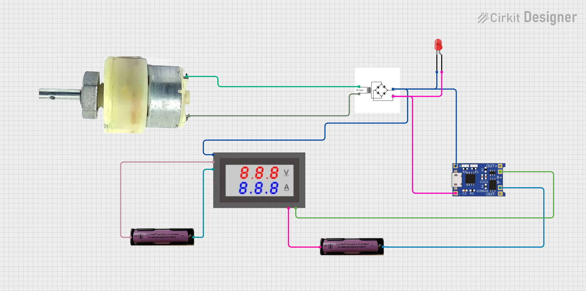
Circuit Documentation
Summary
This circuit consists of a 12V geared motor, a bridge rectifier, a TP4056 battery charging module, a red LED, a mini digital volt/ammeter, and two 3.7V batteries. The circuit is designed to convert AC to DC, charge a battery, and monitor voltage and current.
Component List
Bridge Rectifier
- Description: Converts AC input to DC output.
- Pins: AC input +, AC input -, +, -
LED: Two Pin (red)
- Description: A red LED used for indication.
- Pins: Cathode, Anode
3.7V Battery
- Description: Provides 3.7V DC power.
- Pins: +, -
TP4056
- Description: A battery charging module.
- Pins: OUT-, B-, B+, OUT+, IN-, IN+
12V Geared Motor
- Description: A motor that operates on 12V DC.
- Pins: Terminal 1, Terminal 2
Mini Digital Volt/Ammeter
- Description: Measures voltage and current.
- Pins: Gnd, Vin, Vread, Vsupply
Wiring Details
Bridge Rectifier
- AC input + is connected to Terminal 2 of the 12V Geared Motor.
- AC input - is connected to Terminal 1 of the 12V Geared Motor.
- + is connected to:
- IN+ of the TP4056
- Vread of the Mini Digital Volt/Ammeter
- Cathode of the LED: Two Pin (red)
- - is connected to:
- IN- of the TP4056
- Anode of the LED: Two Pin (red)
LED: Two Pin (red)
- Cathode is connected to + of the Bridge Rectifier.
- Anode is connected to - of the Bridge Rectifier.
3.7V Battery (Instance 1)
- + is connected to Gnd of the Mini Digital Volt/Ammeter.
- - is connected to B- of the TP4056.
3.7V Battery (Instance 2)
- + is connected to Vsupply of the Mini Digital Volt/Ammeter.
- - is connected to Gnd of the Mini Digital Volt/Ammeter.
TP4056
- IN+ is connected to + of the Bridge Rectifier.
- IN- is connected to - of the Bridge Rectifier.
- B- is connected to - of the 3.7V Battery (Instance 1).
- B+ is connected to Vin of the Mini Digital Volt/Ammeter.
12V Geared Motor
- Terminal 1 is connected to AC input - of the Bridge Rectifier.
- Terminal 2 is connected to AC input + of the Bridge Rectifier.
Mini Digital Volt/Ammeter
- Gnd is connected to:
- + of the 3.7V Battery (Instance 1)
- - of the 3.7V Battery (Instance 2)
- Vin is connected to B+ of the TP4056.
- Vread is connected to + of the Bridge Rectifier.
- Vsupply is connected to + of the 3.7V Battery (Instance 2).
Code
There is no code associated with this circuit.