Cirkit Designer
Your all-in-one circuit design IDE
Home /
Project Documentation
Arduino UNO Controlled Tilt Sensor Alarm with LED Indicator
Circuit Documentation
Summary
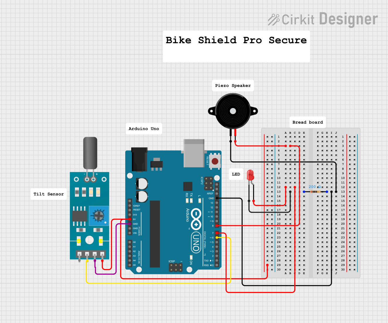
The circuit consists of an Arduino UNO microcontroller interfaced with a tilt sensor, a red two-pin LED, a resistor, and a piezo speaker. The tilt sensor is used to detect orientation changes, which can then be processed by the Arduino to trigger responses such as lighting the LED or emitting a sound through the piezo speaker. The resistor is used to limit the current through the LED to prevent damage. The piezo speaker is connected to the Arduino and can be used to generate sound signals.
Component List
Tilt Sensor
- Pins: A0, D0, GND, VCC
- Description: A sensor that detects orientation changes.
Arduino UNO
- Pins: UNUSED, IOREF, Reset, 3.3V, 5V, GND, Vin, A0-A5, SCL, SDA, AREF, D0-D13
- Description: A microcontroller board based on the ATmega328P.
LED: Two Pin (red)
- Pins: cathode, anode
- Description: A red light-emitting diode.
Resistor
- Pins: pin1, pin2
- Description: A passive two-terminal electrical component that implements electrical resistance.
- Properties: 200 Ohms
Piezo Speaker
- Pins: pin1, pin2
- Description: An electronic device that can be used to generate tones or sounds.
Wiring Details
Tilt Sensor
- VCC connected to Arduino UNO 5V
- D0 connected to Arduino UNO D6
- GND connected to Arduino UNO GND
Arduino UNO
- D7 connected to LED anode
- D8 connected to Piezo Speaker pin2
- GND connected to Resistor pin2, Piezo Speaker pin1, and Tilt Sensor GND
LED: Two Pin (red)
- anode connected to Arduino UNO D7
- cathode connected to Resistor pin1
Resistor
- pin1 connected to LED cathode
- pin2 connected to Arduino UNO GND and Piezo Speaker pin1
Piezo Speaker
- pin1 connected to Arduino UNO GND and Resistor pin2
- pin2 connected to Arduino UNO D8
Documented Code
Arduino UNO Code (sketch.ino)
void setup() {
  // put your setup code here, to run once:

}

void loop() {
  // put your main code here, to run repeatedly:

}
Note: The provided code is a template and does not include specific functionality. It needs to be completed with the logic to interact with the tilt sensor, LED, and piezo speaker based on the circuit's design.