
Circuit Documentation
Summary
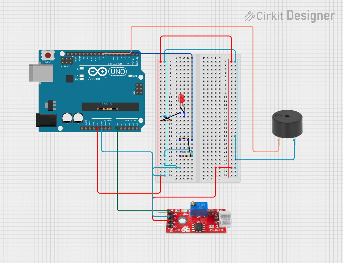
This circuit is designed to interface with a sound sensor, a buzzer, and an LED. The primary function of the circuit is to activate the buzzer when the sound sensor detects noise above a certain threshold. The LED is included in the circuit but is not utilized in the current configuration. The Arduino UNO serves as the central microcontroller, reading the sound sensor's analog output and controlling the buzzer accordingly.
Component List
Arduino UNO
- Description: A microcontroller board based on the ATmega328P.
- Purpose: Acts as the central processing unit for the circuit, reading sensor inputs and controlling outputs.
- Pins: UNUSED, IOREF, Reset, 3.3V, 5V, GND, Vin, A0-A5, SCL, SDA, AREF, D0-D13.
Buzzer
- Description: An electromechanical component that produces sound.
- Purpose: Emits an audible alert when activated by the Arduino.
- Pins: PIN, GND.
Sound Sensor
- Description: A sensor that detects sound levels in the environment.
- Purpose: Provides analog sound level input to the Arduino.
- Pins: Analog, GND, VCC, Digital.
Resistor (200 Ohms)
- Description: A passive two-terminal electrical component that implements electrical resistance.
- Purpose: Used for current limiting or voltage dropping within the circuit.
- Pins: pin1, pin2.
LED: Two Pin (red)
- Description: A red light-emitting diode.
- Purpose: Not used in the current configuration but can be used as an indicator.
- Pins: cathode, anode.
Wiring Details
Arduino UNO
- D2: Connected to a series of resistors.
- 5V: Power supply for the Sound Sensor (VCC).
- GND: Common ground for the Buzzer and Sound Sensor.
- A0: Receives the analog signal from the Sound Sensor (Analog).
- D8: Controls the Buzzer (PIN).
Buzzer
- PIN: Controlled by Arduino UNO (D8).
- GND: Connected to the common ground.
Sound Sensor
- Analog: Connected to Arduino UNO (A0).
- GND: Connected to the common ground.
- VCC: Powered by Arduino UNO (5V).
Resistor (200 Ohms)
- Multiple resistors are used in the circuit, potentially for current limiting purposes. Specific wiring details for each resistor are not provided in the net list.
LED: Two Pin (red)
- cathode: Connected to a resistor.
- anode: Wiring details not provided in the net list.
Documented Code
/*
 * This Arduino sketch is designed to interface with a sound sensor, a buzzer,
 * and an LED. When the sound sensor detects a sound, the buzzer will turn on.
 * The LED is not used in this sketch but is part of the circuit.
 */

// Pin definitions
const int soundSensorPin = A0; // Sound sensor analog output connected to A0
const int buzzerPin = 8;       // Buzzer connected to digital pin 8

void setup() {
  // Initialize the buzzer pin as an output
  pinMode(buzzerPin, OUTPUT);
  // Initialize the sound sensor pin as an input
  pinMode(soundSensorPin, INPUT);
}

void loop() {
  // Read the value from the sound sensor
  int soundValue = analogRead(soundSensorPin);
  // If sound is detected (value above a threshold), turn on the buzzer
  if (soundValue > 500) { // Adjust threshold as needed
    digitalWrite(buzzerPin, HIGH);
  } else {
    digitalWrite(buzzerPin, LOW);
  }
  // Small delay to avoid rapid toggling
  delay(100);
}
Filename: sketch.ino
Description: The code continuously reads the analog value from the sound sensor connected to pin A0. If the value exceeds a predefined threshold (500 in this case), the buzzer connected to pin D8 is turned on. Otherwise, the buzzer is turned off. A short delay is included in the loop to prevent rapid toggling of the buzzer state.