Arduino-Controlled Light Sensing LED Circuit
Circuit Documentation
Summary of the Circuit
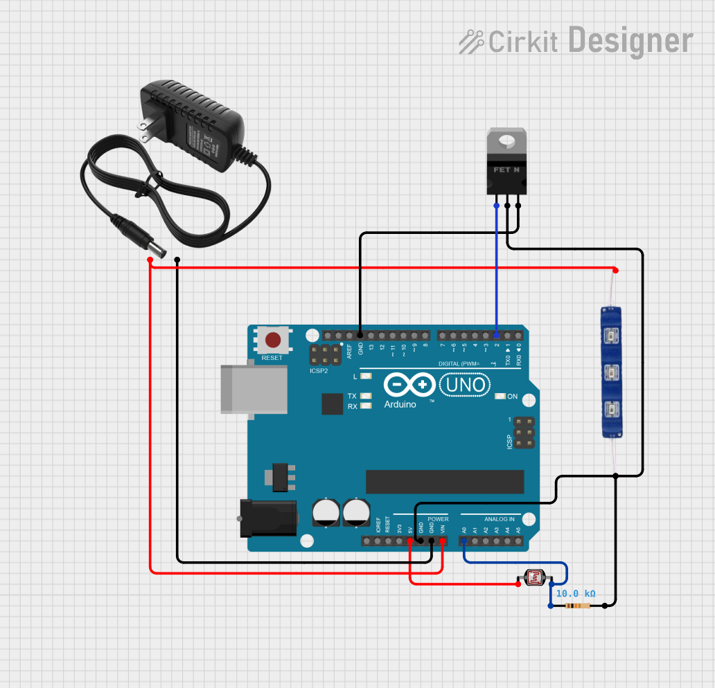
This circuit appears to be designed to control a 12V blue LED using an Arduino UNO based on the ambient light detected by a photocell (LDR). The Arduino UNO is used to read the analog value from the LDR and control the gate of an nMOS transistor, which in turn switches the LED on or off. A resistor is used in series with the LDR to form a voltage divider, and the 12V power supply is used to power the LED and the Arduino UNO.
Component List
Arduino UNO
- Microcontroller board based on the ATmega328P
- It has 14 digital input/output pins, 6 analog inputs, a 16 MHz quartz crystal, a USB connection, a power jack, an ICSP header, and a reset button.
Photocell (LDR)
- A light-dependent resistor whose resistance changes with the amount of light it is exposed to.
12V Power Supply
- Provides a 12V output to power the circuit.
12V Blue LED
- A light-emitting diode that emits blue light when powered by 12V.
Resistor
- A passive two-terminal electrical component with a resistance value of 10,000 Ohms.
nMOS Transistor (MOSFET)
- A type of field-effect transistor that can be used as an electronic switch or amplifier.
Wiring Details
Arduino UNO
- 5V pin is connected to the LDR.
- GND pin is connected to the GND of the 12V power supply, the GND pin of the LED, and the source pin of the MOSFET.
- Vin pin is connected to the + of the 12V power supply and the VCC pin of the LED.
- A0 pin is connected to the junction between the LDR and the resistor.
- D2 pin is connected to the gate of the MOSFET.
Photocell (LDR)
- One pin is connected to the 5V pin of the Arduino UNO.
- The other pin is connected to one end of the resistor and the A0 pin of the Arduino UNO.
12V Power Supply
- pin is connected to the Vin pin of the Arduino UNO and the VCC pin of the LED.
- pin is connected to the GND pin of the Arduino UNO.
12V Blue LED
- VCC pin is connected to the + of the 12V power supply and the Vin pin of the Arduino UNO.
- GND pin is connected to the drain pin of the MOSFET.
Resistor
- One pin is connected to the LDR and the A0 pin of the Arduino UNO.
- The other pin is connected to the drain pin of the MOSFET.
nMOS Transistor (MOSFET)
- Gate pin is connected to the D2 pin of the Arduino UNO.
- Drain pin is connected to the GND pin of the LED and one end of the resistor.
- Source pin is connected to the GND pin of the Arduino UNO.
Documented Code
void setup() {
  // put your setup code here, to run once:

}

void loop() {
  // put your main code here, to run repeatedly:

}
The provided code is a template and does not contain any functional code. To control the LED based on the LDR reading, the setup() function should be configured to initialize the digital pin connected to the MOSFET as an output, and the loop() function should read the analog value from the LDR and turn the LED on or off based on a threshold value.