
Arduino UNO Based Weight Measurement and Display System with Keypad Control and Relay Output
View and Edit Project In Cirkit Designer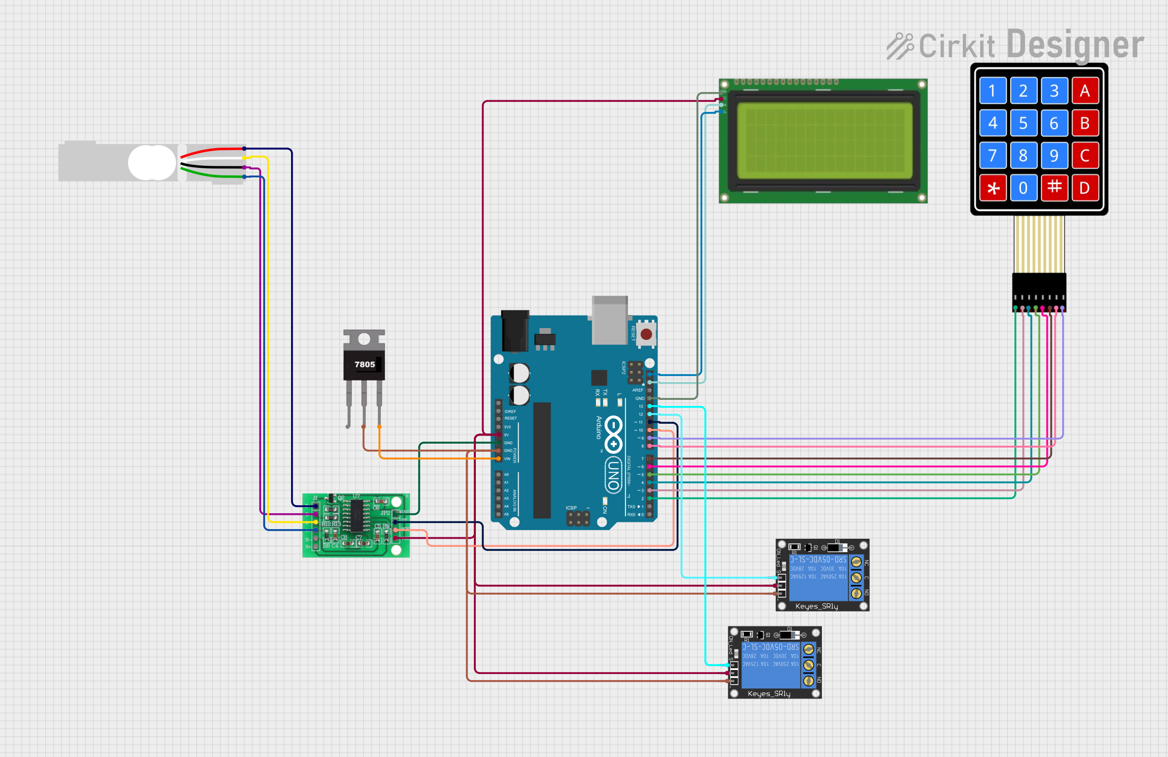
Circuit Documentation
Summary
This circuit integrates various components controlled by an Arduino UNO microcontroller to perform a specific set of functions. The circuit includes a load cell interfaced with an HX711 bridge sensor interface for weight measurement, a 20x4 LCD with I2C for display, a 4x4 membrane matrix keypad for user input, and two 1-channel 5V 10A relays for controlling external loads. A 7805 voltage regulator is used to provide a stable 5V supply to the Arduino UNO.
Component List
Arduino UNO
- Microcontroller board based on the ATmega328P
- It has 14 digital input/output pins, 6 analog inputs, a 16 MHz quartz crystal, a USB connection, a power jack, an ICSP header, and a reset button.
Load Cell - Red/white/black/green
- A transducer that converts force into an electrical signal.
- It has four wires corresponding to Excitation+ (E+), Excitation- (E-), Signal+ (A+), and Signal- (A-).
HX711 - Bridge Sensor Interface
- A precision 24-bit analog-to-digital converter (ADC) designed for weigh scales and industrial control applications to interface directly with a bridge sensor.
- It has multiple input and power pins, including E+, E-, A-, A+, B-, B+, GND, DATA (OUT), SCK (CLOCK IN), and a 3.3/3.5V supply.
Lcd 20x4 i2c
- A 20x4 character LCD display with an I2C interface module.
- It has four pins: GND, 5V, SCA, and SCL.
4X4 Membrane Matrix Keypad
- A 16-button keypad that provides a user interface for input.
- It has eight pins corresponding to four rows (R1 to R4) and four columns (C1 to C4).
1-Channel Relay (5V 10A)
- An electromechanical switch that allows a low-power signal to control a higher power circuit.
- It has six pins: Normally Closed (NC), signal, Common (C), power, Normally Open (NO), and ground.
7805 Voltage Regulator
- A voltage regulator that outputs a stable 5V from a higher voltage input.
- It has three pins: Voltage Input (Vin), Ground (Gnd), and Voltage Output (Vout).
Wiring Details
Arduino UNO
- 5V connected to the 5V power rail supplying power to other components.
- GND connected to the ground rail for a common ground reference.
- Digital pins D2 to D13 are used for interfacing with the keypad, relays, and HX711 module.
- Analog pins A4 (SDA) and A5 (SCL) are used for I2C communication with the LCD display.
- Vin connected to the output of the 7805 voltage regulator to supply regulated 5V power.
Load Cell
- E+, A-, E-, A+ connected to the corresponding pins on the HX711 module to transmit the load cell signals.
HX711 - Bridge Sensor Interface
- E+, E-, A-, A+ connected to the load cell for signal measurement.
- GND connected to the ground rail.
- DATA (OUT) connected to Arduino pin D11 for data output.
- SCK (CLOCK IN) connected to Arduino pin D10 for clock input.
- 3.3/3.5V Supply connected to the 5V power rail.
Lcd 20x4 i2c
- GND connected to the ground rail.
- 5V connected to the 5V power rail.
- SCA connected to Arduino pin A4 (SDA).
- SCL connected to Arduino pin A5 (SCL).
4X4 Membrane Matrix Keypad
- R1 to R4 connected to Arduino pins D2 to D5 respectively.
- C1 to C4 connected to Arduino pins D6 to D9 respectively.
1-Channel Relay (5V 10A)
- Ground connected to the ground rail.
- Power connected to the 5V power rail.
- Signal connected to Arduino pins D12 and D13 for the two relays to control them independently.
7805 Voltage Regulator
- Vin connected to an unregulated voltage source (higher than 5V).
- Gnd connected to the ground rail.
- Vout connected to Arduino Vin pin to supply regulated 5V power.
Documented Code
The code for the Arduino UNO microcontroller is not provided in the input. However, the typical structure of an Arduino sketch (sketch.ino) includes setup and loop functions, where setup is used for initializing settings, and loop contains the main functionality that runs continuously.
void setup() {
  // Initialize digital pins, I2C interface, serial communication, etc.
}

void loop() {
  // Main code to interact with the keypad, read from the load cell, control relays, and update the LCD display.
}
For detailed code implementation, the actual code content needs to be provided. The documentation.txt file is mentioned but does not contain code content as per the input provided.