ESP32-Based Smart Scale and Environmental Sensor System

Circuit Documentation
Summary
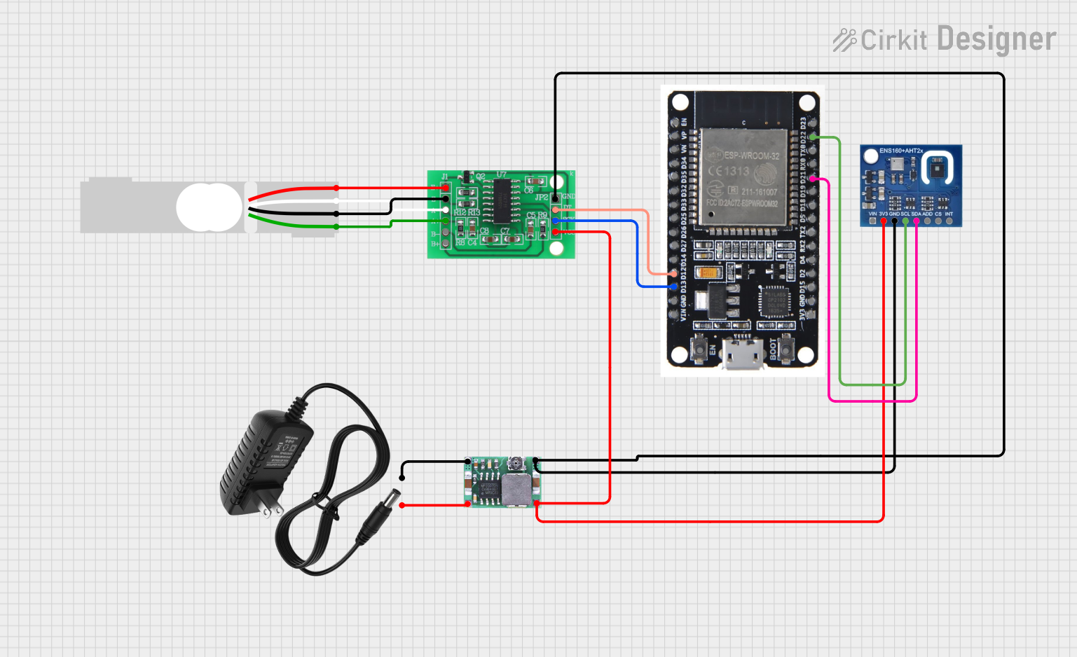
This circuit is designed to measure weight using a Load Cell and process the signal through an HX711 Bridge Sensor Interface. The processed signal is then read by an ESP32 microcontroller, which also interfaces with an ENS160+AHT21 sensor to measure temperature and humidity. The ESP32 communicates with the HX711 via digital pins and with the ENS160+AHT21 sensor via I2C protocol. A Mini-360 DC-DC Step Down Buck Converter is used to step down the voltage from a 12v power supply to a lower voltage suitable for powering the components.
Component List
Load Cell - Red/white/black/green
- Description: A sensor used to measure weight or force.
- Pins: E+, A-, E-, A+
HX711 - Bridge Sensor Interface
- Description: A precision 24-bit analog-to-digital converter (ADC) designed for weigh scales and industrial control applications to interface directly with a bridge sensor.
- Pins: E+, E-, A-, A+, B-, B+, GND, DATA (OUT), SCK (CLOCK IN), 3.3/3.5V Supply
ESP32
- Description: A microcontroller with Wi-Fi and Bluetooth capabilities, suitable for a variety of applications and IoT projects.
- Pins: EN, VP, VN, D34, D35, D32, D33, D25, D26, D27, D14, D12, D13, GND, VIN, 3V3, D15, D2, D4, RX2, TX2, D5, D18, D19, D21, RX0, TX0, D22, D23, BOOT
ENS160+AHT21
- Description: A sensor module that combines gas sensing (ENS160) with temperature and humidity sensing (AHT21).
- Pins: VIN, 3V3, GND, SCL, SDA, ADD, CS, INT
Mini-360 DC-DC Step Down Buck Converter
- Description: A compact module that converts a higher voltage DC input to a lower voltage DC output with high efficiency.
- Pins: Input -, Input +, Output +, Output -
12v Power Supply
- Description: Provides a 12V DC output to power electronic components and circuits.
- Pins: +, -
Wiring Details
Load Cell - Red/white/black/green
- E+ connected to HX711 E+
- A- connected to HX711 A-
- E- connected to HX711 E-
- A+ connected to HX711 A+
HX711 - Bridge Sensor Interface
- E+, E-, A-, A+ connected to corresponding Load Cell pins
- GND connected to ENS160+AHT21 GND and Mini-360 DC-DC Step Down Buck Converter Output -
- DATA (OUT) connected to ESP32 D12
- SCK (CLOCK IN) connected to ESP32 D13
- 3.3/3.5V Supply connected to ENS160+AHT21 3V3 and Mini-360 DC-DC Step Down Buck Converter Output +
ESP32
- D12 connected to HX711 DATA (OUT)
- D13 connected to HX711 SCK (CLOCK IN)
- D21 (I2C SDA) connected to ENS160+AHT21 SDA
- D22 (I2C SCL) connected to ENS160+AHT21 SCL
ENS160+AHT21
- 3V3 connected to HX711 3.3/3.5V Supply and Mini-360 DC-DC Step Down Buck Converter Output +
- GND connected to HX711 GND
- SDA connected to ESP32 D21
- SCL connected to ESP32 D22
Mini-360 DC-DC Step Down Buck Converter
- Input - connected to 12v Power Supply -
- Input + connected to 12v Power Supply +
- Output + connected to HX711 3.3/3.5V Supply and ENS160+AHT21 3V3
- Output - connected to HX711 GND
12v Power Supply
- connected to Mini-360 DC-DC Step Down Buck Converter Input +
- connected to Mini-360 DC-DC Step Down Buck Converter Input -
Documented Code
#include <HX711.h>
#include <Wire.h>
#include <Adafruit_Sensor.h>
#include <Adafruit_AHTX0.h>

// HX711 pins
#define HX711_DOUT 12
#define HX711_SCK 13

// I2C pins for ENS160+AHT21
#define I2C_SDA 21
#define I2C_SCL 22

// Create instances
HX711 scale;
Adafruit_AHTX0 aht;

void setup() {
  // Initialize Serial Monitor
  Serial.begin(115200);

  // Initialize HX711
  scale.begin(HX711_DOUT, HX711_SCK);
  Serial.println("HX711 initialized.");

  // Initialize I2C for ENS160+AHT21
  Wire.begin(I2C_SDA, I2C_SCL);
  if (!aht.begin()) {
    Serial.println("Failed to find AHT sensor!");
    while (1) delay(10);
  }
  Serial.println("AHT sensor initialized.");
}

void loop() {
  // Read weight from HX711
  if (scale.is_ready()) {
    long reading = scale.read();
    Serial.print("HX711 reading: ");
    Serial.println(reading);
  } else {
    Serial.println("HX711 not found.");
  }

  // Read temperature and humidity from AHT21
  sensors_event_t humidity, temp;
  aht.getEvent(&humidity, &temp);
  Serial.print("Temperature: ");
  Serial.print(temp.temperature);
  Serial.println(" degrees C");
  Serial.print("Humidity: ");
  Serial.print(humidity.relative_humidity);
  Serial.println("% rH");

  // Delay between readings
  delay(2000);
}
This code is responsible for initializing the HX711 and ENS160+AHT21 sensors, reading data from them, and outputting the readings to the Serial Monitor. The HX711 is interfaced using digital pins D12 and D13 for data and clock, respectively. The ENS160+AHT21 sensor is interfaced using I2C with pins D21 for SDA and D22 for SCL. The code includes error handling for sensor initialization and a delay between readings to allow for stable measurements.