
Arduino Nano-Based AC Power Monitoring and Control System with GSM Reporting
View and Edit Project In Cirkit Designer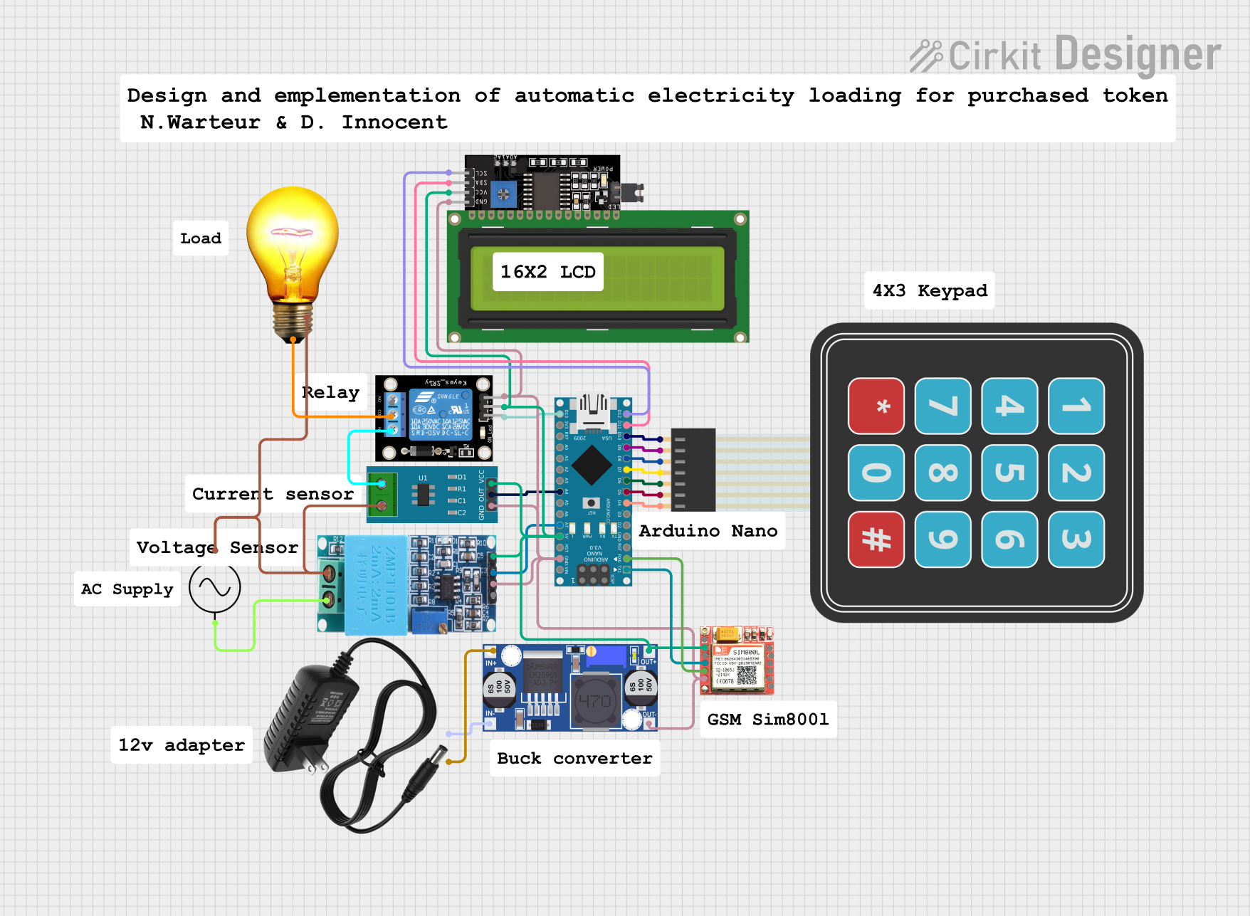
Circuit Documentation
Summary
This circuit integrates various components to perform a set of functions that likely involve sensing current, controlling an AC bulb, interfacing with a user through a keypad and LCD display, and communicating via the SIM800L module. An Arduino Nano serves as the central microcontroller, interfacing with sensors, a relay module, a display, and a communication module. The circuit is powered by a 12V power supply, which is stepped down to the required voltages using a buck converter.
Component List
ZMPT101B
- Description: Voltage sensor module for AC voltages.
- Pins: OUT, GND, VCC, NEUTRO, FASE
Arduino Nano
- Description: A compact microcontroller board based on the ATmega328P.
- Pins: D1/TX, D0/RX, RESET, GND, D2, D3, D4, D5, D6, D7, D8, D9, D10, D11/MOSI, D12/MISO, VIN, 5V, A7, A6, A5, A4, A3, A2, A1, A0, AREF, 3V3, D13/SCK
KY-019 Relay Module 1 Channel
- Description: A single-channel relay module for controlling high power/high voltage devices.
- Pins: S, 5V, GND, NC, COM, NO
Current Sensor 5A
- Description: A sensor for measuring electrical current up to 5A.
- Pins: 1, 2, GND, OUT, VCC
Membrane Matrix Keypad
- Description: A simple interface for user input using a matrix keypad.
- Pins: Row 1, Row 2, Row 3, Row 4, Column 1, Column 2, Column 3
LCD Display 16x4 I2C
- Description: An alphanumeric liquid crystal display with an I2C interface.
- Pins: SCL, SDA, VCC, GND
AC Bulb
- Description: A standard AC-powered light bulb.
- Pins: P, N
SIM800L
- Description: A GSM/GPRS module for cellular communication.
- Pins: NFT, RING, VCC, DTR, RST, MIC +, RXD, MIC-, TXD, SPK+, GND, SPK-
Buck Converter
- Description: A DC-DC converter to step down voltage levels.
- Pins: IN+, IN-, OUT+, OUT-
AC Supply
- Description: The main AC power source for the circuit.
- Pins: +ve, -ve
12V Power Supply
- Description: A power supply providing a 12V output.
- Pins: +, -
Wiring Details
ZMPT101B
- OUT connected to Arduino Nano A7
- GND connected to common ground
- VCC connected to common 5V
- NEUTRO connected to AC Supply +ve, Current Sensor 5A pin 2, and AC Bulb N
- FASE connected to AC Supply -ve
Arduino Nano
- A7 connected to ZMPT101B OUT
- GND connected to common ground
- 5V connected to common 5V
- D1/TX connected to SIM800L RXD
- D0/RX connected to SIM800L TXD
- D4 to D10 connected to Membrane Matrix Keypad Column 3 to Row 1 respectively
- D11/MOSI connected to LCD Display 16x4 I2C SDA
- D12/MISO connected to LCD Display 16x4 I2C SCL
- A4 connected to Current Sensor 5A OUT
- D13/SCK connected to KY-019 Relay Module 1 Channel S
KY-019 Relay Module 1 Channel
- S connected to Arduino Nano D13/SCK
- 5V connected to common 5V
- GND connected to common ground
- NC connected to Current Sensor 5A pin 1
- COM connected to AC Bulb P
Current Sensor 5A
- 1 connected to KY-019 Relay Module 1 Channel NC
- 2 connected to ZMPT101B NEUTRO
- GND connected to common ground
- OUT connected to Arduino Nano A4
- VCC connected to common 5V
Membrane Matrix Keypad
- Column 1 to Column 3 connected to Arduino Nano D6 to D4
- Row 1 to Row 4 connected to Arduino Nano D10 to D7
LCD Display 16x4 I2C
- SCL connected to Arduino Nano D12/MISO
- SDA connected to Arduino Nano D11/MOSI
- VCC connected to common 5V
- GND connected to common ground
AC Bulb
- P connected to KY-019 Relay Module 1 Channel COM
- N connected to ZMPT101B NEUTRO
SIM800L
- GND connected to common ground
- VCC connected to common 5V
- RXD connected to Arduino Nano D1/TX
- TXD connected to Arduino Nano D0/RX
Buck Converter
- IN+ connected to 12V Power Supply +
- IN- connected to 12V Power Supply -
- OUT+ connected to common 5V
- OUT- connected to common ground
AC Supply
- +ve connected to ZMPT101B NEUTRO
- -ve connected to ZMPT101B FASE
12V Power Supply
-
- connected to Buck Converter IN+
-
- connected to Buck Converter IN-
Documented Code
Arduino Nano Code (sketch.ino)
void setup() {
  // put your setup code here, to run once:

}

void loop() {
  // put your main code here, to run repeatedly:

}
Additional Notes (documentation.txt)
No additional code documentation was provided.