
ESP32-Based Smart Irrigation System with Wi-Fi Control and Soil Moisture Sensors
View and Edit Project In Cirkit Designer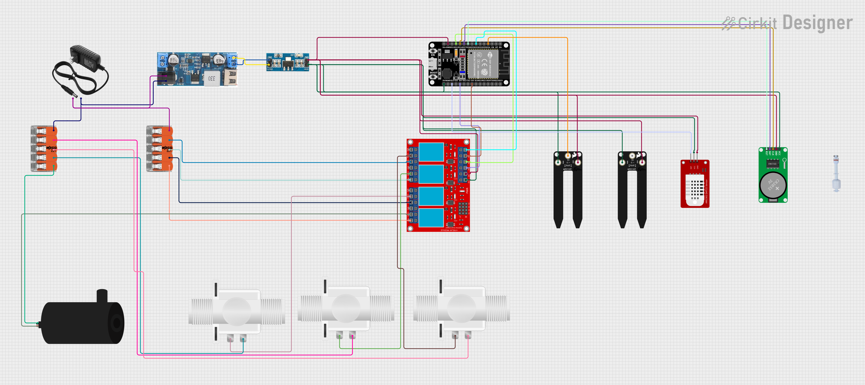
Circuit Documentation
Summary
This document provides a detailed overview of an irrigation system circuit. The system is designed to automate the watering process using various sensors, relays, and actuators controlled by an ESP32 microcontroller. The system includes soil moisture sensors, a DHT22 temperature and humidity sensor, a real-time clock (RTC), a water pump, and solenoid valves. The ESP32 microcontroller is programmed to read sensor data, control the water pump and valves, and communicate with a server for remote monitoring and control.
Component List
Splicing connector WAGO 221
- Description: A splicing connector used for connecting multiple wires.
- Pins: Port 1, Port 2, Port 3, Port 4, Port 5
12V Power Supply
- Description: Provides 12V DC power to the circuit.
- Pins: +, -
DCDC 12V/5V 3A
- Description: Converts 12V DC to 5V DC.
- Pins: 12V (+), GND, 5V (+), Vin (+), Vin (-)
3.3V Converter
- Description: Converts 5V DC to 3.3V DC.
- Pins: GND, Vout, Vin
ESP32 (30 pin)
- Description: A microcontroller with WiFi and Bluetooth capabilities.
- Pins: EN, VP, VN, D34, D35, D32, D33, D25, D26, D27, D14, D12, D13, GND, Vin, D23, D22, TX0, RX0, D21, D19, D18, D5, TX2, RX2, D4, D2, D15, 3V3
Water Pump
- Description: A pump used to move water through the irrigation system.
- Pins: Positive, Negative
4 Channel Relay Module
- Description: A relay module used to control high-power devices.
- Pins: N.O. 4, COM 4, N.C. 4, N.O. 3, COM 3, N.C. 3, N.O. 2, COM 2, N.C. 2, N.O. 1, COM 1, N.C. 1, Pin 13, Pin 14, Pin 15, Pin 16, Pin 17, Pin 18, Pin 19, Pin 20, Pin 21, Pin 22, Pin 23, Pin 24, VCC+, VCC- (GND), IN 1, IN 2, IN 3, IN 4
Plastic Solenoid Valve
- Description: A valve used to control the flow of water.
- Pins: Pin1, Pin2
SparkFun gator:soil
- Description: A soil moisture sensor.
- Pins: VCC, GND, SIG
DHT22
- Description: A temperature and humidity sensor.
- Pins: GND, VCC, DAT
RTC-DS1302
- Description: A real-time clock module.
- Pins: Vcc, GND, CLK, DAT, RST
Float Switch
- Description: A switch used to detect the presence of water.
- Pins: GND, Digital Pin
Wiring Details
Splicing connector WAGO 221
- Port 1: Connected to the negative pin of the water pump.
- Port 2: Connected to pin2 of a Plastic Solenoid Valve.
- Port 3: Connected to pin2 of another Plastic Solenoid Valve.
- Port 4: Connected to pin2 of another Plastic Solenoid Valve.
- Port 5: Connected to the GND pin of the 12V power supply and the GND pin of the DCDC 12V/5V 3A converter.
12V Power Supply
- +: Connected to the 12V (+) pin of the DCDC 12V/5V 3A converter.
- -: Connected to the GND pin of the DCDC 12V/5V 3A converter.
DCDC 12V/5V 3A
- 12V (+): Connected to the + pin of the 12V power supply.
- GND: Connected to the GND pin of the 12V power supply.
- 5V (+): Connected to the Vout pin of the 3.3V converter.
- Vin (+): Not connected.
- Vin (-): Not connected.
3.3V Converter
- GND: Connected to the GND pin of the DCDC 12V/5V 3A converter.
- Vout: Connected to the 5V (+) pin of the DCDC 12V/5V 3A converter.
- Vin: Connected to the 3V3 pin of the ESP32 microcontroller.
ESP32 (30 pin)
- D34: Connected to the SIG pin of the SparkFun gator:soil sensor.
- D33: Connected to the IN 4 pin of the 4 channel relay module.
- D26: Connected to the RST pin of the RTC-DS1302 module.
- D27: Connected to the DAT pin of the RTC-DS1302 module.
- D14: Connected to the CLK pin of the RTC-DS1302 module.
- D12: Connected to the IN 2 pin of the 4 channel relay module.
- GND: Connected to the GND pin of the 3.3V converter.
- D5: Connected to the IN 3 pin of the 4 channel relay module.
- D4: Connected to the IN 1 pin of the 4 channel relay module.
- D15: Connected to the DAT pin of the DHT22 sensor.
- 3V3: Connected to the Vin pin of the 3.3V converter.
Water Pump
- Positive: Connected to the COM 1 pin of the 4 channel relay module.
- Negative: Connected to Port 1 of the Splicing connector WAGO 221.
4 Channel Relay Module
- IN 4: Connected to the D33 pin of the ESP32 microcontroller.
- IN 2: Connected to the D12 pin of the ESP32 microcontroller.
- IN 3: Connected to the D5 pin of the ESP32 microcontroller.
- IN 1: Connected to the D4 pin of the ESP32 microcontroller.
- COM 4: Connected to pin1 of a Plastic Solenoid Valve.
- N.C. 4: Connected to Port 4 of the Splicing connector WAGO 221.
- COM 3: Connected to pin1 of another Plastic Solenoid Valve.
- N.C. 3: Connected to Port 3 of the Splicing connector WAGO 221.
- COM 2: Connected to pin1 of another Plastic Solenoid Valve.
- N.C. 2: Connected to Port 2 of the Splicing connector WAGO 221.
- COM 1: Connected to the positive pin of the water pump.
- N.C. 1: Connected to Port 1 of the Splicing connector WAGO 221.
- VCC+: Connected to the VCC pin of the 3.3V converter.
- VCC- (GND): Connected to the GND pin of the 3.3V converter.
Plastic Solenoid Valve
- Pin1: Connected to the COM pin of the respective relay channel.
- Pin2: Connected to the respective port of the Splicing connector WAGO 221.
SparkFun gator:soil
- VCC: Connected to the 3V3 pin of the ESP32 microcontroller.
- GND: Connected to the GND pin of the 3.3V converter.
- SIG: Connected to the D34 pin of the ESP32 microcontroller.
DHT22
- GND: Connected to the GND pin of the 3.3V converter.
- VCC: Connected to the 3V3 pin of the ESP32 microcontroller.
- DAT: Connected to the D15 pin of the ESP32 microcontroller.
RTC-DS1302
- Vcc: Connected to the 3V3 pin of the ESP32 microcontroller.
- GND: Connected to the GND pin of the 3.3V converter.
- CLK: Connected to the D14 pin of the ESP32 microcontroller.
- DAT: Connected to the D27 pin of the ESP32 microcontroller.
- RST: Connected to the D26 pin of the ESP32 microcontroller.
Float Switch
- GND: Not connected.
- Digital Pin: Not connected.
Documented Code
ESP32 (30 pin) Code
#include <Arduino.h>
#include <WiFi.h>
#include <WiFiMulti.h>
#include <WiFi