ESP32-CAM Based Wi-Fi Controlled Security System with Face Recognition
Circuit Documentation
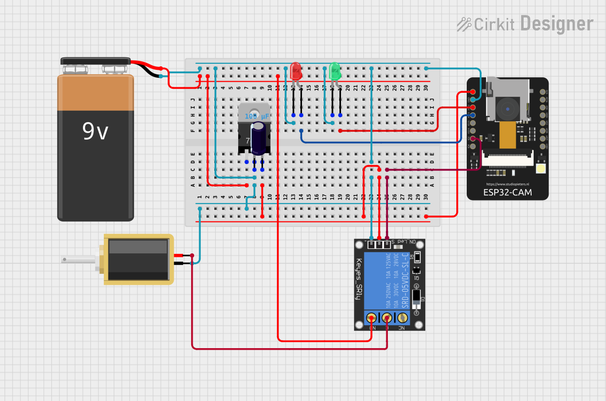
Summary
The circuit in question is designed to incorporate an ESP32-CAM module, which is a small camera module with Wi-Fi capabilities, along with a solenoid, voltage regulator, LEDs, a relay module, and a 9V battery. The ESP32-CAM is responsible for image capture and processing, and it can control other components based on the image analysis results. The solenoid and relay module are likely used for actuating a lock mechanism, while the LEDs provide visual feedback. The voltage regulator ensures that the ESP32-CAM and other components receive the correct voltage levels for operation.
Component List
ESP32-CAM
- Description: A small-sized ESP32-based board with a camera module and Wi-Fi capabilities.
- Purpose: Captures images and processes them for applications such as face recognition, and controls other components wirelessly.
Solenoid
- Description: An electromechanical device used as an actuator.
- Purpose: Likely used to actuate a locking mechanism when triggered by the ESP32-CAM.
Voltage Regulator (V_REG_LD1117VXX)
- Description: A low-dropout voltage regulator with a fixed or adjustable output.
- Purpose: Provides a stable voltage supply to the ESP32-CAM and potentially other components.
LEDs (Green and Red)
- Description: Two-pin light-emitting diodes, one green and one red.
- Purpose: Provides visual feedback, possibly indicating system status or recognition results.
1-Channel Relay (5V 10A)
- Description: An electromechanical switch that can be controlled by the ESP32-CAM.
- Purpose: Controls the power supply to the solenoid, allowing for electronic actuation.
9V Battery
- Description: A standard 9V battery.
- Purpose: Provides power to the circuit.
Electrolytic Capacitor
- Description: A polarized capacitor with a capacitance value of 0.0001 Farads.
- Purpose: Stabilizes the voltage supply and filters out noise from the power source.
Wiring Details
ESP32-CAM
- 5V: Connected to the voltage regulator's output (V_REG_LD1117VXX OUT pin).
- GND: Common ground with the voltage regulator, solenoid, relay module, and LEDs.
- IO12: Connected to the green LED anode.
- IO13: Connected to the red LED anode.
- IO2: Connected to the relay module signal pin.
Solenoid
- Pin1: Connected to the relay module normally open (NO) pin.
- Pin2: Connected to the relay module common (C) pin.
Voltage Regulator (V_REG_LD1117VXX)
- IN: Connected to the 9V battery positive terminal.
- OUT: Connected to the ESP32-CAM 5V pin and the electrolytic capacitor negative terminal.
- GND: Common ground with the ESP32-CAM, solenoid, relay module, and LEDs.
LEDs (Green and Red)
- Green LED Anode: Connected to ESP32-CAM IO12.
- Green LED Cathode: Common ground.
- Red LED Anode: Connected to ESP32-CAM IO13.
- Red LED Cathode: Common ground.
1-Channel Relay (5V 10A)
- NC: Not connected.
- Signal: Connected to ESP32-CAM IO2.
- C: Connected to solenoid pin2.
- Power: Connected to the voltage regulator output (V_REG_LD1117VXX OUT pin).
- NO: Connected to solenoid pin1.
- Ground: Common ground.
9V Battery
- Positive: Connected to the voltage regulator input (V_REG_LD1117VXX IN pin).
- Negative: Common ground.
Electrolytic Capacitor
- Positive: Connected to the voltage regulator input (V_REG_LD1117VXX IN pin).
- Negative: Connected to the voltage regulator output (V_REG_LD1117VXX OUT pin).
Documented Code
The code provided is for the ESP32-CAM module and includes several components:
esp_camera.h: Library for camera configuration and image capture.WiFi.h: Library for Wi-Fi connectivity.camera_pins.h: Defines pin assignments for different camera models.app_httpd.h: Contains the HTTP server setup and handlers for the camera web server.camera_index.h: Contains the HTML index page served by the camera web server.
The main functionality of the code is to initialize the camera, connect to Wi-Fi, and start a web server that provides a live video stream and the ability to capture images. The server also allows for control over camera settings and face recognition features.
Face recognition is implemented using the fd_forward.h and fr_forward.h libraries, which handle face detection and recognition, respectively. The code can enroll new faces and recognize them later.
The ESP32-CAM module's GPIOs are used to control the LEDs and relay module, which in turn controls the solenoid. The green LED indicates a successful face recognition, while the red LED indicates no match found. The relay activates the solenoid when a recognized face is detected.
The code also includes handling for different camera models and configurations, ensuring compatibility with various ESP32-CAM board layouts.