
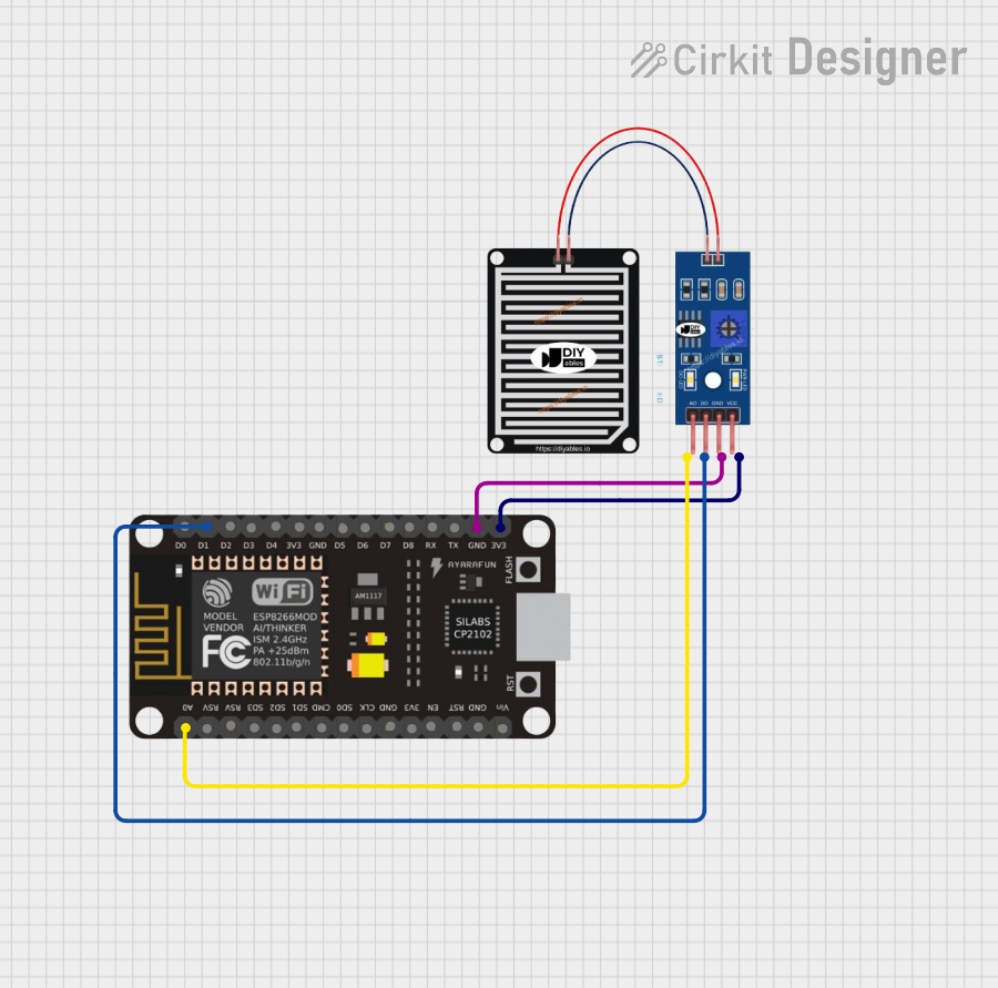
Circuit Documentation
Summary
This document provides a detailed overview of a circuit that integrates an ESP8266 NodeMCU microcontroller with a rain sensor. The circuit is designed to detect rain and trigger a buzzer when rain is detected. The ESP8266 NodeMCU reads the digital output from the rain sensor and controls the buzzer accordingly. Additionally, the microcontroller outputs the status (raining or not raining) to the serial monitor.
Component List
ESP8266 NodeMCU
- Description: A low-cost Wi-Fi microcontroller with GPIO, ADC, and other features.
- Pins: D0, D1, D2, D3, D4, 3V3, GND, D5, D6, D7, D8, RX, TX, A0, RSV, SD3, SD2, SD1, CMD, SD0, CLK, EN, RST, VIN
Rain Sensor
- Description: A sensor module that detects rain and provides both analog and digital outputs.
- Pins: AO, DO, GRD, VCC
Wiring Details
ESP8266 NodeMCU
- D1: Connected to DO of the Rain Sensor
- GND: Connected to GRD of the Rain Sensor
- 3V3: Connected to VCC of the Rain Sensor
- A0: Connected to AO of the Rain Sensor
Rain Sensor
- DO: Connected to D1 of the ESP8266 NodeMCU
- GRD: Connected to GND of the ESP8266 NodeMCU
- VCC: Connected to 3V3 of the ESP8266 NodeMCU
- AO: Connected to A0 of the ESP8266 NodeMCU
Documented Code
ESP8266 NodeMCU Code
void setup() {
  // put your setup code here, to run once:
  #define rsensor D1
  #define buzzer D3
  pinMode(rsensor, INPUT);
  pinMode(buzzer, OUTPUT);
  Serial.begin(9600);
}

void loop() {
  // put your main code here, to run repeatedly:
  if (0 == digitalRead(rsensor)) {
    digitalWrite(buzzer, HIGH);
    Serial.println("Raining .............");
    delay(1000);
  } else {
    digitalWrite(buzzer, LOW);
    Serial.println("No Raining .............");
    delay(1000);
  }
}
Rain Sensor Code
void setup() {
  // put your setup code here, to run once:

}

void loop() {
  // put your main code here, to run repeatedly:

}
This documentation provides a comprehensive overview of the circuit, including the components used, their wiring details, and the code running on the microcontrollers.