
Circuit Documentation
Summary of the Circuit
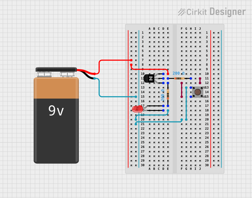
This circuit appears to be a simple switch-controlled LED lighting system with a transistor acting as a switch. The LED is powered by a 9V battery and controlled by a pushbutton. The NPN transistor is used to enable or disable the current flow to the LED. There are two resistors in the circuit, likely serving as current-limiting resistors for the LED and the base of the transistor.
Component List
NPN Transistor (EBC)
- Description: A standard NPN bipolar junction transistor with emitter, base, and collector pins.
- Purpose: Acts as an electronic switch in the circuit.
Resistor
- Description: A passive two-terminal electrical component that implements electrical resistance as a circuit element.
- Properties: 200 Ohms resistance.
- Purpose: Limits the current flowing through the LED and provides the necessary biasing to the transistor's base.
LED: Two Pin (red)
- Description: A two-pin light-emitting diode that emits red light.
- Purpose: Acts as the visual indicator when powered.
Pushbutton
- Description: A simple switch mechanism for controlling some aspect of a machine or a process.
- Purpose: Allows the user to control the lighting of the LED.
9V Battery
- Description: A standard 9V battery with positive and negative terminals.
- Purpose: Provides the power source for the circuit.
Wiring Details
NPN Transistor (EBC)
- Collector: Connected to the positive terminal of the 9V battery.
- Emitter: Connected to one of the pins of a 200 Ohm resistor.
- Base: Connected to one of the pins of another 200 Ohm resistor.
Resistor (200 Ohms)
- Pin1: One resistor is connected to the base of the NPN transistor, and the other is connected to the anode of the LED.
- Pin2: One resistor is connected to the pushbutton, and the other is connected to the emitter of the NPN transistor.
LED: Two Pin (red)
- Anode: Connected to one of the pins of a 200 Ohm resistor.
- Cathode: Connected to the negative terminal of the 9V battery through the pushbutton.
Pushbutton
- Pin 1 (in): Connected to one of the pins of a 200 Ohm resistor.
- Pin 3 (out): Connected to the negative terminal of the 9V battery and the cathode of the LED.
9V Battery
- +: Connected to the collector of the NPN transistor.
- -: Connected to the pushbutton and the cathode of the LED through the pushbutton.
Documented Code
There is no embedded code provided for this circuit as it does not contain any programmable components or microcontrollers. The operation of the circuit is purely hardware-based, relying on the physical state of the pushbutton to control the lighting of the LED.