
Circuit Documentation
Summary
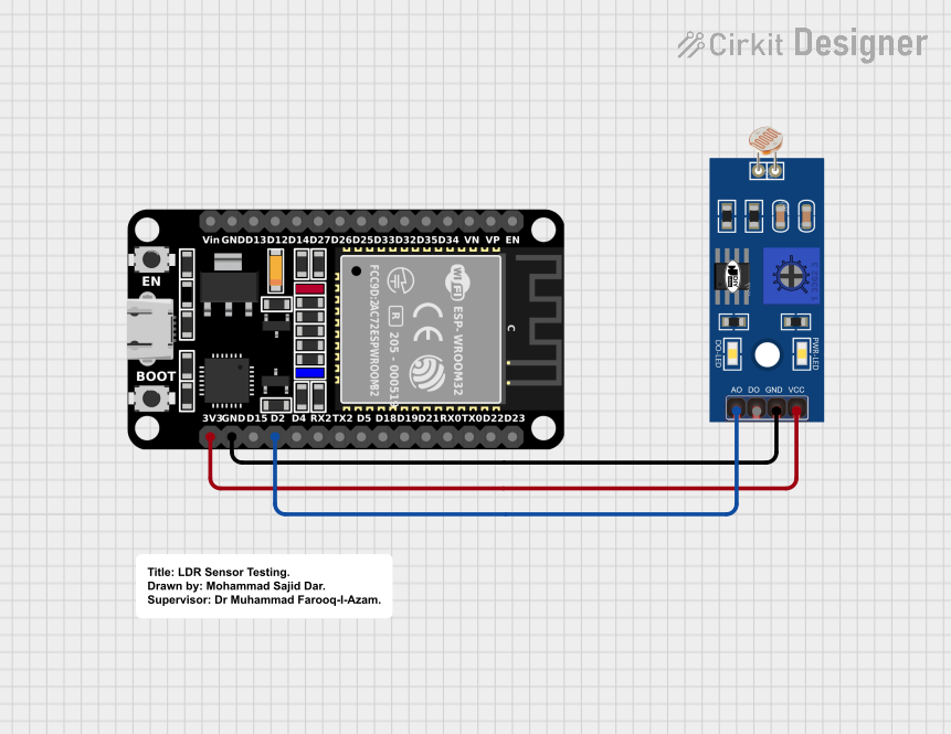
This document provides a detailed overview of a circuit that includes an ESP32 microcontroller and an LDR (Light Dependent Resistor). The ESP32 is used to read the analog signal from the LDR, which varies with the intensity of light. The circuit is powered by the 3.3V output from the ESP32.
Component List
ESP32 (30 pin)
- Description: A powerful microcontroller with built-in Wi-Fi and Bluetooth capabilities.
- Pins: EN, VP, VN, D34, D35, D32, D33, D25, D26, D27, D14, D12, D13, GND, Vin, D23, D22, TX0, RX0, D21, D19, D18, D5, TX2, RX2, D4, D2, D15, 3V3
LDR (Light Dependent Resistor)
- Description: A resistor whose resistance decreases with increasing incident light intensity.
- Pins: A0, D0, GND, VCC
Comment
- Description: A placeholder for comments or notes in the circuit design.
- Pins: None
Wiring Details
ESP32 (30 pin)
- D2: Connected to A0 of the LDR
- GND: Connected to GND of the LDR
- 3V3: Connected to VCC of the LDR
LDR (Light Dependent Resistor)
- A0: Connected to D2 of the ESP32
- GND: Connected to GND of the ESP32
- VCC: Connected to 3V3 of the ESP32
Code
There is no code provided for this circuit.
This document provides a comprehensive overview of the components and their connections in the circuit. The ESP32 reads the analog signal from the LDR, which varies with the light intensity, allowing for light-sensitive applications.